
- Home
- Products
-
Information
- Catalogues
- Compliance
- Datasheets
-
Technology
- Browse Technologies
-
Application Notes
- Blowout Magnets - What They Are & Why Use Them
- Contact Resistance Versus Pressure
- Contacts Construction & Materials
- EV Battery Charging Applications - Relays & Contactors
- HVDC Relays & Contactors Conductor Size & Heat Dissipation
- HVDC Relays & Contactors Overview
- Latching Relays
- Layman's Guide to Coil Suppression
- Relay Contact Forms - An Explanation
- Switching Polarised & Non Polarised
- Installation
- User Manuals
- Whitepapers
- Videos
- Applications
- About us
-
News & Events
-
Latest News
- All our Latest News
- Managing Relay Vibration in Industrial Vehicle Control Systems
- The Physics Wall
- How Advanced Relay Contact Design Transforms Forklift Reliability
- OEM Finland Oy at Helsinki's Teknologia '25
- TMS Elektronik at EV Charge - Istanbul
- Jinzon at Energy Taiwan 2025
- New HVDC Contactor 800A @ 1500VDC
- The Great Relay Debate
- iVT Expo Germany reflections
- Custom or Standard?
- The Relay - More than just a simple black box
- ACT Expo 2025
- Enhancing energy efficiency in contactors and relays for mobile applications
- Navigating market dynamics: a power control industry perspective
- Forklift Revolution - Keeping you informed
- Durakool Distributor Conference
- Enhancing Energy Efficiency in Modern Electrical Systems
- Durakool at Detroit Battery Show 2024
- Unveiling relay solutions for EV and industrial applications
- Ensure Your Forklift Relays Don't Fail - Learn How!
- iVT Cologne - Electrification
- Absolutely worth the visit
- Istanbul EV Charge
- Engineering & Design Show 2023 - Excellent Show
- Durakool in Gothenburg
- HVDC Range Expansion 2023
- Product launch at Stuttgart Battery Show 2023
- Teamwork Appreciation - Las Vegas
- Durakool in the Fast Lane at Silverstone
- Valuable time spent with our customers
- Intro Durakool Pre-Charge & Discharge Resistors
- Great Success 2022 Battery Show
- Socking it to you!
- Dig Yourself Out of a Hole
- Keep Your Cool at the Wheel
- Need a Socket to Go with That Relay?
- Events
-
Press Releases
- All our Latest Press Releases
- Breakthrough DLVC200 and DLVC300 contactors from Durakool boost performance and reliability
- Durakool launches new high-performance DG86M relay
- Durakool unveils first-of-kind relay solution for electric vehicle and industrial applications
- Optimised, safe & reliable solutions from Durakool - iVT Expo
- Durakool Announces Expansion of High Voltage DC Portfolio
- Durakool Announces High Voltage DC Switching Contactors for Superior Isolation, Improved Reliability and Longer Service Life
- AUTOMOTIVE HIGH VOLTAGE - TWO IN ONE!
- Move Up in the World with DG38L PCB Motor Control Relays
-
Latest News
- Contact us
- Portal
Industrial & DC Relay User Manual
Industrial & DC Relay User Manual
Document Scope
This manual covers installation, operation and safety guidance for the following Durakool relay series:
DC20, D2RS, D2RH, D2RG, DG34, DG38, DG38B, DM84, DM85, DM87, DX84, DX85, DX87, DX2, DX3, DX4
These relays are intended for industrial control and DC switching applications. Depending on model, configurations include PCB mount, panel mount and sealed variants.
1. Introduction and application responsibility
Relays operate in real world conditions, not in a lab. Temperature, vibration, contamination, wiring practice and switching duty can all affect performance and service life.
Before final use and release:
Refer to and analyse the specific datasheet of the relay before proceeding further.
Test the relay across the practical operating range of your application.
Verify performance in the real end-use environment, under actual loads and duty cycle.
Confirm the relay is suitable for the intended use as part of your system risk assessment.
Important
Datasheet specification values are reference information based on sample evaluation and measurement.
Figures, graphs and life data are not guaranteed values and can change with load type, circuit design and environment.
2. Safety precautions
WARNING: Risk of electric shock, fire, or explosion
Installation, inspection and servicing must be carried out by trained and qualified personnel.
Do not exceed specified limits (coil, contacts, switching life, duty cycle and environmental ratings). Refer to the product datasheet. Exceeding these ratings can cause overheating, smoke, or fire.
Before installing, wiring, inspecting, servicing, or troubleshooting:
Switch OFF and isolate all power supplies.
Confirm the circuit is de-energised.
Do not touch live parts.
Follow the internal connection diagram and terminal identification in the datasheet. Poor wiring or soldering can cause malfunction, overheating, or fire.
Install in accordance with applicable national electrical installation regulations.
Where failure could create a hazard:
Design to be fail-safe.
Add independent protective measures.
Provide short-circuit and over current protection.
Do not use relays in areas with flammable or explosive gas / vapour. Switching arcs and heat can ignite hazardous atmospheres.
Do not drop, strike, modify, or disassemble the relay. Damage can reduce performance and increase failure risk.
Validate relay behaviour in the final product under actual loads and operating conditions before release.
3. Understanding technical specifications
Always use the datasheet for your exact part number. Typical ranges across models (vary by variant) include:
Coil supply: 5 to 110VDC or 6 to 230VAC.
Operating temperature: -40°C to +85°C.
Electrical endurance: defined by load category in the datasheet.
Before selection and installation, confirm real application conditions match the installation environment.
Review the selection checklist (points 3.1, 3.2, 3.3, 3.4 and 3.5).
3.1 Coil
Confirm:
Rated coil voltage and type (AC / DC) and duty.
Operate and release voltage / current.
Maximum coil voltage / current (including tolerance).
Coil resistance and expected temperature rise.
Note:
Allow for supply ripple and start-up voltage drop.
At high ambient temperatures, include coil self-heating and hot-start conditions.
If using transistor / MOSFET drive, confirm drive margin and suppression / protection.
Under-driven coils may not pull-in reliably.
Over voltage can overheat and permanently damage the coil.
3.2 Contacts
Confirm:
Contact arrangement (SPST, SPDT, etc.).
Rating for your load type (resistive, inductive, capacitive, etc.).
Contact material and resistance.
Electrical life at the stated load category.
Note:
Match contact material to the load, especially for inductive and capacitive loads.
Take extra care with low-level loads (risk of unstable contact performance).
Higher temperatures typically reduce life, validate within application.
Switching behaviour can change if switching occurs near AC zero-crossing or synchronised conditions, validate within application.
3.3 Operation
Confirm:
Operate time, release time, bounce time.
Switching frequency limits.
Switching-capacity curves / graphs, where provided.
Note:
Operate / release / bounce vary with applied voltage and temperature.
High switching frequency reduces expected life.
Treat switching-capacity graphs as guidance, validate on real equipment.
3.4 Environment
Confirm:
Vibration resistance and shock resistance.
Ambient temperature.
Contamination risk (protection level).
Note:
Verify vibration and shock within your application build.
For high-temperature use, select a relay with a higher-temperature-rated coil winding (heat-resistant insulated wire).
For harsh or contaminated atmospheres, use a sealed type.
3.5 Other
Confirm:
Dielectric strength.
Mounting method and terminal style.
Size / weight.
Note:
Check any application-specific conditions (mounting orientation limits, clearance / creepage, heat sources, etc.).
Check for correct terminal style: plug-in / socket, PCB, solder, tab terminals, or screw terminals.
4. Relay care
4.1 Handling
Handle relays carefully.
Do not apply undue force to terminals.
Do not mount, store, or handle relays in a way that applies external force (bending, tension, compression).
Do not remove the relay case. It is part of the relay design and performance cannot be guaranteed if it is removed.
Do not disassemble, repair, or modify the relay.
4.2 Environment and contamination
Use a clean, dry environment with normal temperature and humidity, low dust, and minimal corrosive gases (for example SO2, H2S) and organic vapours.
Do not install the relay in:
Direct sunlight.
Ambient temperature outside specification.
Humidity outside specification, or rapid temperature changes that cause condensation.
Excess dust, salt mist, metal powder, or magnetic dust.
Vibration or shock above rated limits.
Exposure to water, oil, chemicals, solvents, or spray.
If these conditions cannot be avoided, specify a plastic-sealed, or metal hermetically sealed relay, as appropriate.
For plastic sealed relays in particular, take note they are:
Not designed for high airtightness applications.
Suitable near sea level, avoid use outside approx. 86 to 106 kPa.
Not suitable for flammable / explosive atmospheres (use hermetically sealed relays).
CAUTION: Silicone contamination
Do not use silicone-based resins, sealants, or coatings near the relay.
Silicone contamination can cause contact failure, including in sealed relays.
4.3 Electrial use
Wire the coil with correct polarity where + and - are marked (for example DC relays with diode, magnet or indicator).
Apply rated coil voltage and keep coil voltage within datasheet limits.
Do not exceed contact voltage, current, or switching ratings.
Switching capacity and life figures are typical values. Actual life depends on load type and conditions.
Confirm the relay is correctly and securely mounted before operation.
Design the system so current can be interrupted in an emergency to prevent fire spread.
Replace relays at intervals appropriate to the safety function and duty cycle.
4.4 Temperature, shock and vibration
Stay within the ambient temperature range in the datasheet.
Do not exceed vibration and shock limits.
Mount away from vibration sources (motors, compressors) and secure to prevent abnormal vibration.
For long-term vibration environments (for example electric vehicles), avoid sockets where practical. Instead consider direct soldering to PCB.
4.5 Magnetic fields
Do not use in external magnetic fields of 800 A/m or higher (for example near transformers or magnets).
Strong fields can distort arcs and lead to flashover, tracking, insulation faults, or malfunction, especially in polarised relays.
Keep distance, choose mounting position carefully, and verify in the final product.
4.6 Soldering and cleaning
For automated soldering, specify flux-resistant or fully sealed relays to prevent flux ingress.
If cleaning is required on sealed relays, use alcohol-based solvent.
Do not use ultrasonic cleaning unless the relay is specifically designed for it.
4.7 Terminals, mounting and sockets
Wire the coil with correct polarity where + and - are marked (for example DC relays with diode, magnet or indicator).
For tab terminals, a general insertion force guide is 40 to 70 N (approximately 4 to 7 kgf).
Do not bend terminals.
Do not straighten or reuse deformed terminals.
When using a socket, confirm relay and socket ratings are compatible for your standard and application.
4.8 Test lever (where fitted)
Do not press the test lever unintentionally.
Use only for checks, for e.g. continuity.
4.9 Replacement and repair
WARNING: Before replacing a relay or carrying out wiring:
Switch OFF coil and load supplies.
Confirm isolation and no residual voltage.
Proceed only when safe.
5. Mounting
5.1 Pre-checks
Before fitting:
Confirm the part number matches the specified item.
Confirm coil rating (voltage / type) is correct.
Do not install if either detail is incorrect.
5.2 Orientation and direction
For PCB relays, terminal wiring diagrams identify top / bottom. Mount in the specified orientation as shown in fig. 1 below to ensure correct operation and rated performance.
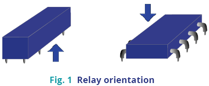 Relay with terminals viewed from the bottom (Terminals cannot be seen from the top).
Relay with terminals viewed from the top (All terminals can be seen from the top).
Note: During PC Board pattern design (NC relay).
If there is no fixed mounting direction, where practical:
Orient the relay so contact travel and moving parts run perpendicular to expected vibration / shock direction as shown in fig. 2 below.
CAUTION: Form B (NC) contacts - note that vibration / shock behaviour can change depending on orientation when the coil is not energised.
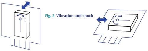
Mount the relay so fixed and moving contact faces are vertical where possible. This helps prevent dust, arc debris and powdered metal from settling on contact surfaces.
5.3 Avoid switching high-load and low-level switching
Do not use one relay for both high loads and low-level signals where avoidable. High-load switching can contaminate contacts and cause low-level failures.
If unavoidable:
Do not mount with low-level contacts positioned below high-load contacts.
5.4 Adjacency
When relays are mounted close together, heat can increase local temperature beyond normal.
Check datasheet clearance requirements if specified. Otherwise, calculate based on testing within application as this would need to be worked out depending on specific physical and environmental constraints.
Apply the same spacing rules for multiple PCBs in card racks.
Verify ambient temperature so the relay stays within limits.
Polarised relays mounted too close together can alter operating characteristics. Verify operation in the final assembly.
If noise-sensitive equipment (for example a microcontroller) is installed close to relays, include suitable layout and suppression. Arcing noise can cause control malfunction.
5.5 Insulation
Maintain adequate creepage and clearance distance between each terminal and earth (ground).
5.6 Dimensions
Use maximum stated dimensions (including tolerances) when designing PCB layout and clearances.
5.7 Installation
For plug-in relays:
Do not remove the cover. It serves a functional purpose and is not intended to be removed during normal handling.
Do not reuse or straighten deformed terminals. Using a damaged terminal can apply excessive force to the relay and may permanently affect performance.
For panel relays:
Use flat washers under fixings to prevent damage during tightening.
Tighten to 0.49 to 0.686 N·m (equivalent to 5 to 7 kgf·cm).
Fit a spring washer to reduce loosening over time.
For quick-connect terminals:
Recommended insertion force guide is 40 to 70 N (4 to 7 kgf).
Do not solder lead wires directly to tab terminals (risk of internal deformation and flux ingress).
For terminal sockets:
Verify relay and socket ratings before use and operate with margin.
Mount the socket firmly and tighten screws fully.
Use only specified Durakool sockets, where required, for ideal fit and thermal performance.
Never insert or remove a relay while the circuit is energised.
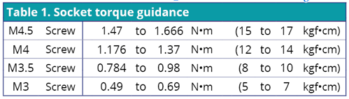
For screw terminals, clamp conductors correctly and tighten within socket torque specification, as per table 1 below:
 For lead wiring:
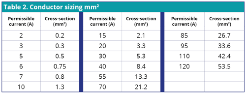
Select conductor size to match load current.
Use at least the minimum cross-sectional area specified in table 2 below.
Undersized wire can overheat and damage insulation.
 For PCB relays:
Follow common industry standard practice.
Choose suitable PCB materials and thickness to reduce risk of solder joint cracking.
Consider hole size and land diameter to ensure secure fitting.
Follow appropriate steps for soldering control and take the necessary precautions when placing, applying flux, preheating, transporting, soldering, cooling, cleaning and coating of the relay.
6. Operation - Input (coil)
6.1 Selection and limits
Do not exceed specified limits (coil, contacts, switching life, duty cycle and select coil voltage / type (AC or DC) to match the control circuit.
Incorrect coils can prevent rated performance.
6.2 Voltage
Use rated coil voltage for reliable operation.
Do not exceed maximum coil voltage in the datasheet.
Maximum coil voltage is an absolute limit, not a continuous operating value. Applying higher voltage than specified can overheat and burn out the coil.
Must-operate and must-release values are typically at 23°C. Hot-start, long run periods and high ambient temperature can prevent these values being met.
Design the control circuit so rated voltage is present at the coil terminals, not just at the supply. Allow for wiring drops, driver drops and supply dips / spikes.
If the supply dips when multiple relays energise together, improve supply capacity rather than raising voltage beyond rated range.
5V system → 4.5V coil
3V system → 2.4V coil
Transistor-driver guide (allowance for voltage drop):
Drive the coil with a clean ON / OFF signal (square / rectangular waveform).
Avoid slow ramp-up or ramp-down (risk of chatter, delayed timing, bounce and welding).
6.3 Current
Prevent leakage current reaching the coil when de-energised.
If leakage cannot be eliminated, add a blocking / diverting circuit.
6.4 Temperature rise
Do not operate outside datasheet ambient temperature range.
If switched OFF then ON immediately, assume coil remains hot.
Hot coils have higher resistance and may require higher voltage to operate.
Copper coil resistance increases by about 0.4% per 1°C (guide only).
Note: In some polarised relays, the change may be smaller.
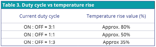
Pulse drive behaviour depends on duration and duty cycle. See page 13 for guide:
Note: Refer to Durakool Application Note on 'Temperature & its effect on Electro Mechanical Relay Operation.'
6.5 Stray circuits (bypass circuits / sneak current)
Design sequence circuits to prevent unintended current paths which can cause humming, failure to release, or abnormal operation.
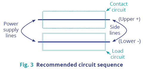
Layout:
Use two power supply lines.
Upper line: positive (+).
Lower line: negative (-).
For AC, use the same layout concept. Copper coil resistance increases by about 0.4% per 1°C (guide only).
Connect on positive side:
Relay contacts.
Timer contacts.
Limit switches.
Connect on negative side:
Relay coils
Timer coils
Magnet coils
Solenoid coils
Motors
Lamps
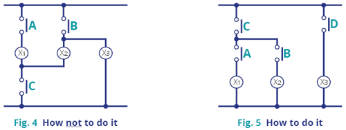
For DC circuits, a diode may be used where appropriate to prevent stray current.
6.6 Long coil wiring
For plug-in relays:
Do not run control and power wiring in the same conduit over long distances.
Note: induced voltage can hold the relay ON or prevent reset. Long runs also increase risk from voltage drop and external transients (for example lightning).
Measure coil voltage at the relay terminals under actual operating conditions.
Select / adjust supply so the coil at the relay receives rated voltage.
Note: cable capacitance can leave residual voltage after switch-off and delay release.
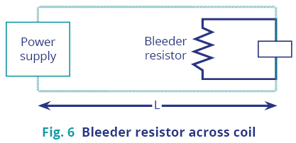
If release issues occur, fit a bleeder (bypass) resistor across coil terminals at the relay.
6.7 Preventing switch-off surges
When the coil is switched OFF, back-EMF can damage semiconductors and cause unreliable operation.
Do not run control and power wiring in the same conduit over long distances. Fit surge suppression at the coil terminals, or use a relay with built-in suppression where specified.
Note: suppression can increase release time, so verify in your circuit.
Specific coil suppression topology’s such as diode or resistor need to be discussed, dependent on application and drive circuitry.
Note: For more detail on this subject, refer to Durakool Application Note on 'A Layman’s guide to coil suppression'.
6.8 Preventing electrolytic corrosion in relay coils
In hot / humid environments or for long energised periods, grounding a coil can cause electrolytic corrosion and coil failure.
Recommended wiring to reduce risk:
Bond the positive (+) side of the supply to chassis / earth.
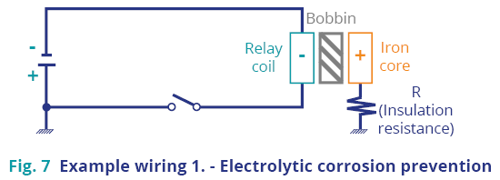
If negative (–) must be grounded, or earthing is not possible, place the control switch / contact in the positive (+) supply line.
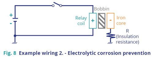
If no chassis / earth is used, connect the 'ground' terminal to the positive (+) side of the coil.
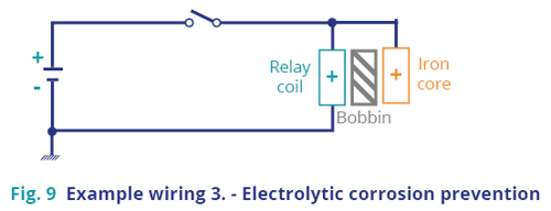
If negative (–) is grounded, do not fit a switch / contact in the negative (–) supply line.
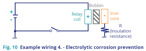
6.9 Indicators (where fitted)
Some models include built-in:
LED indicator: DX2, DX3, DX4, D2R*
Mechanical flag: DX2, DX3, DX4, D2R*
Note: Indicators show coil energisation only. They do not confirm contact switching.
6.10 AC Coil guidelines
Confirm rated voltage and frequency match the available supply.
Mechanical flag: DX2, DX3, DX4, D2R*.
Note: AC coils are intended for 50/60 Hz operation. Running at other frequencies is outside the relay’s approved operating conditions and may invalidate certifications and performance claims. AC coils typically run hotter than equivalent DC coils.
Keep coil voltage within ±10% to 15% of rated value.
Note: under voltage can cause buzzing / chatter and overheating. Over voltage increases heating and wear.
Use a true sine-wave supply where possible. Distorted waveforms can increase hum and coil heating.

Note: Supply dips from motors / solenoids / transformers can cause chatter and contact damage. Risk increases with small transformers, long runs, thin wiring.
Size supply / wiring for combined inrush, if multiple relays energise together. AC coils draw high inrush at pull-in.
Operate time varies with AC phase at energisation, so it is specified as a range. Ensure sequencing cannot be affected.
For small relays, up to ~½ cycle (≈10 ms at 50 Hz).
For larger relays, up to ~1 cycle (≈20 ms at 50 Hz).
Measure coil voltage and waveform at the relay during real switching conditions if buzzing / chatter / overheating occurs.
Note: corrective actions may include:
Improve supply, wiring or increase transformer capacity,
Separate the coil supply from heavy loads.
Select a relay with more suitable coil characteristics.
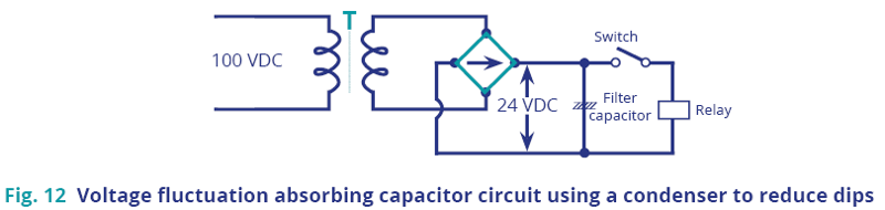
Add a capacitor / smoothing where appropriate. Confirm capacitor sizing by testing under real load conditions. As a guide, for relay with ~1W coil, use ≥5µF.
Note: Supply dips from motors / solenoids / transformers can cause chatter and contact damage. Risk increases with small transformers, long runs, thin wiring.
For a half-wave rectifier do not use without a smoothing capacitor.
For a full-wave rectifier, it may be acceptable without extra smoothing in some circuits, but not all. Verify use within application.
6.7 DC coil guidelines
DC coils are supplied in standard voltages (5, 6, 12, 24, 48, 80 VDC).
Treat stated operate current as minimum pick-up, under ideal conditions only. Allow for tolerance and heating.
Size the drive so available coil current is typically 1.5 to 2×, the stated operate current in worst-case conditions.
Apply rated coil voltage at the coil terminals and keep within ±5%.
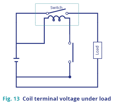
Note: If the coil and load share a supply, load switching (especially high inrush loads) can pull the supply down. Measure the coil terminal voltage with the load operating and confirm it stays within the specified range. See fig. 13 below.
Use a clean DC drive with fast ON and OFF. Avoid slowly rising / falling coil current.
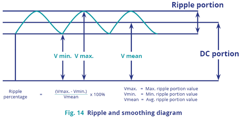
Use a well-smoothed DC supply (battery, or rectified supply with smoothing).
Note: Performance figures are measured using a DC supply with ≤1% ripple. Keep DC ripple to ≤5% and validate if ripple is higher.
Polarity
Check coil terminals and + / − before wiring
Note: Polarised relays will not operate with reversed polarity. Reverse polarity can cause malfunction, shorting, or failure where a diode / LED is fitted.
Power reduction
To reduce coil consumption, use a pull-in boost then a lower hold voltage (DC reduction or PWM).
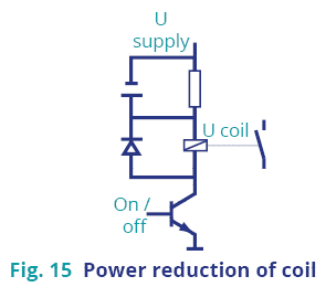
Pull-in: 1.0 to 1.5× rated voltage for ≥100 ms.
PWM: 10 to 25 kHz.
Duty: 50% to 70%. Contact Durakool if below 50%.
Fit a continuous current free-wheel diode across the coil.
7. Operation - Output (contacts)
7.1 Contact life
Contact ratings are stated for specific load types.
Always match rating to your load and required life depending on:
Contact material.
Switched voltage / current (including make / break waveform).
Load type (resistive, inductive, capacitive, etc.).
Switching rate.
Contact form arrangement.
Switching speed and bounce time.
Atmosphere and contamination.
Note: For certified relays, the rating printed on the case is the approved value for that standard.
7.2 Switching duty
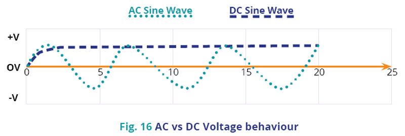
AC current crosses zero each cycle, helping arcs to self-extinguish. DC has no zero-crossing, so arcing is more severe. Expect lower DC ratings for the same relay.
Infrequent switching
If the relay switches once a month or less:
Carry out regular contact checks (continuity / contact resistance tests). Organic films can form on contacts during long idle periods.
Set check frequency based on environment and duty.
Frequent switching
If switching rate is too high, contact arcing can cause welding or shorting between contacts.
Verify performance under real voltage / current / load conditions.
7.3 Current
Inrush current is critical and often the limiting factor (motors, lamps, capacitors).
Measure both steady-state current and inrush current
Do not exceed these ratings.
Note: Overload can cause sustained arcing, carbon build-up, tracking, sticking, or welded contacts.
Published ratings are a starting point. Switching capacity is often based on resistive loads. For inductive, capacitive, or unusual duties, verify by test or proven application data on the actual equipment.
Minimum load figures are guidance only. Validate in real conditions.
Note: If the circuit carries current for long periods without relay movement (for example monitoring using Form B contacts), avoid leaving the coil energised continuously. Use a latching relay where suitable.
7.4 Materials
Use the guidance below to match material to load rating and environment. Where low-level switching is required, select materials / finishes suited to dry circuits and contamination risk.
Material
AgNi0.15 (Fine silver or fine grain silver):
Silver with 0.15% Nickel.
Universal but welds easily.
Sensitive to atmospheric sulphur, so often available with Au flashing.
1V to 150V, 50mA to 100A, >1W.
Resistive loads and loads switched not under power. General purpose use.
AgNi 90/10 (Silver Nickel):
Silver with 10% Nickel.
Important general purpose material with reduced susceptibility to welding.
Good general purpose replacement for AgCdO.
Approximately 6V to 380V, 10mA to 100A.
Excellent for resistive loads with some inductive capability. A good “all-rounder”.
Ag (Silver):
Very high electrical and thermal conductivity, low contact resistance, low cost and widely used.
Can form a sulphide film in sulphur-containing atmospheres. Take care on low voltage / low current circuits.
AgSnO2 (Silver tin oxide):
Excellent resistance to welding.
Very good AC & DC performance.
Good replacement for AgCdO in power switching.
More expensive than AgNi 90/10.
>12V to >380V, >0.5A, >10W.
Good for motor, lamp and capacitive loads. Good general purpose use.
Like silver, can form a sulphide film in sulphur-containing atmospheres.
AgSnOInO (Silver tin indium oxide):
More advanced version of AgSnO2.
Excellent general purpose power switching.
Highly resistant to welding.
Good DC performance.
>12V to >380V, >0.5A, >10W.
Excellent for DC motor loads. Good for lamp and capacitive loads. Good general purpose material.
Surface finish
Au plating (Gold plating):
Similar benefit to gold clad.
Typically, a gold layer >2um, and may be as much as 10um (unusually) thick.
Gold acts as a switching surface and is very good at switching low level signals with repeatability.
Will be damaged if exposed to arcs and is not recommended for switching non-resistive loads and not for high currents.
5V, 2mA, 10mW up to 24V, 62.5mA, 1.5W.
Care is needed with the gold plating process to ensure an even and consistent plating.
Au flash plating (Thin gold film):
Flash is defined as a very thin (<0.3um) layer of gold plating.
Mainly protects the base metal during storage (switch/device). A thin surface layer may be applied to the contact rivet to prevent atmospheric contamination and tarnishing while the relay is in storage.
Once the contacts begin switching, this layer wears away very quickly. It is removed by normal arcing and even with no arc, by the wiping action, as the contacts close and open.
After the coating has been removed, the base contact material carries out the switching of the load.
Contact material transfer
Arcing can cause pits and build-up making the surfaces across contacts rough and uneven, increasing resistance and causing contacts to weld (electrical or mechanical interlock), especially with:
High DC current (especially one-way DC).
Inductive loads (motors, coils, solenoids).
Capacitive loads.
High inrush loads.
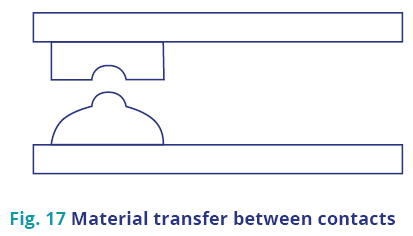
Use suitable suppression and select contact materials resistant to transfer where appropriate.
7.5 Load Type
Some models include built-in:
The load type being switched affects the likelihood of contact welding.
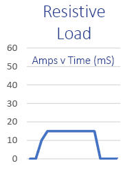
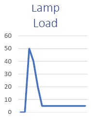
See below load type profiles and inrush ratios versus steady-state.
Resistive (~1x)
Nice and easy. No significant inrush.
Lamp (10-15x)
Large inrush at turn on (cold filament). 10-15x Discharge lamp circuits (tube, transformer, choke, capacitor, etc.) can be higher, typically 20–40× where supply impedance is low (especially high power factor types).
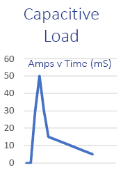
Capacitive (20-40x)
Large inrush tailing off as capacitor charges up.
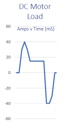
DC Motor (5-10x)
Long peak as motor turns then settles until turn off, when motor acts like a generator and a big, long arc forms across contacts, until motor stops running. Duty becomes more severe with plugging or inching (frequent starts / stops and direction changes). For DC motor + brake control on-inrush, running current and brake, current can vary depending on whether the motor is free-running or stalled / locked. With non-polarised relays, using a Form B (NC) contact for DC braking may also reduce mechanical life, due to brake current. Measure current under real operating conditions.
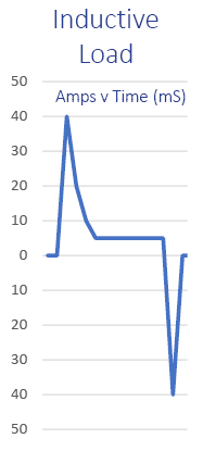
Inductive (10-20x)
Large inrush until magnetic field established then settles, big peak at turn off from stored energy in coil. High inductance can keep the arc going longer when switching off, increasing contact wear.
Transformer (5-15x)
For very small analogue loads, or where contact resistance must stay below 100mΩ (for example measurement or wireless applications), the switching current may be too small to maintain stable contact conduction.
Use relays with twin contacts which generally gives more reliable operation than single contacts, because they provide parallel redundancy.
Use countermeasures such as a dummy resistor in parallel with the load.
7.6 Contact & load wiring
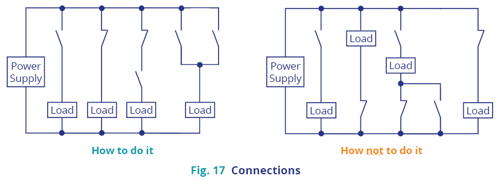
Contact polarity wiring
Keep all relay contacts on the same supply polarity and connect the load on the opposite polarity.
Where a relay has more than one contact pair, aim to keep every contact pair tied to the same supply side.
Do not wire contacts to both sides of the supply and do not mix supply polarity across poles / contact pairs.
Note: This limits voltage across open contacts and reduces risk of arcing between poles in multi-pole relays.
Avoid short circuits in multi-pole relays
Miniature and multi-pole relays may have small internal creepage and clearance between poles.
If different voltages can appear on adjacent poles:
Select a relay with adequate internal insulation and arc barriers.
Do not rely on circuit diagrams alone, check relay construction / specification.
Minimise voltage differences between poles.
Wiring in parallel or series
Parallel wiring can improve reliability but does not increase rating.
Contacts may not make / break at the same time.
Ensure load is shared and stay within current / voltage limits.
Check for bypass / leakage current paths.
Avoid NO–NC short circuits
In compact relays, NO (Form A) and NC (Form B) may be close together and arcing can bridge between them.
Do not wire the circuit so that NO / NC / SPDT paths can short together (e.g. forward and reverse motor drive), as during changeover, a short-circuit current may briefly flow.
Use a mechanically / electrically interlocked forward / reverse solution (see figure 18 below).
If using two relays, set a dead time between contact 1 and contact 2 so they cannot close at the same time.
Note: if a contact welds or a control fault occurs, protection and ratings must prevent wiring overload or component overheating.
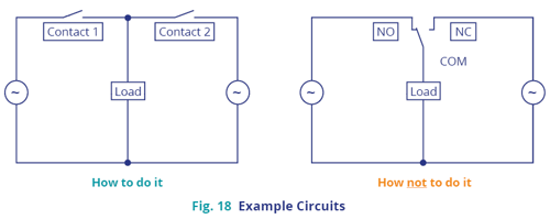
Mixed loads
Do not mix high loads and low loads on the same relay. Use separate relays where possible.
If unavoidable, mount low-load contacts above high-load contacts to reduce contamination.
Note: Reliability will be significantly reduced.
Long contact wiring
If contact wiring exceeds 10m, cable capacitance can create a high inrush at switching.
Fit a 10 to 50Ω series resistor in the contact circuit to limit this surge.
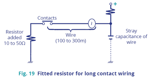
7.7 Electrical life
High temperature reduces electrical contact life. Validate endurance under real load and operating temperature.
Datasheet switching-life and failure-rate figures are guidance only and are based on defined test conditions. Real results vary with:
Coil drive method.
Load.
Switching frequency.
AC switching phase behaviour.
Ambient conditions.
Validate in the actual circuit and environment before release.
7.8 AC Load guidelines
Phase synchronised switching
If contacts always make / break at the same point on the AC waveform, wear increases and early failure can occur. Timer, microcontroller, or thyristor control can synchronise switching unintentionally.
Use random-phase switching and do not synchronise relay drive timing to the AC phase.
Datasheet electrical-life ratings assume random switching. Verify performance within application.
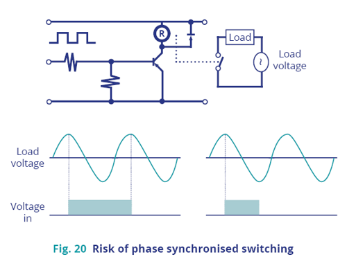
Note: AC relays are intended for 50 / 60 Hz operation. Running at other frequencies is outside the relay’s approved operating conditions and may invalidate certifications and performance claims.
7.9 DC Load guidelines
High voltage DC load guidelines
If contacts always make / break at the same point on the AC waveform, wear increases and early failure can occur. Timer, micro controller, or thyristor control can synchronise switching unintentionally.
Design the system so the DC supply can be switched off within 1 second and include fail-safe measures.
Corrosion during high frequency DC switching
Repeated high-frequency DC switching can produce corrosion due to arcing by-products. Avoid repeated arcing at high switching frequency.
8. Storage
Keep out of direct sunlight.
Store at normal ambient conditions as per datasheet specification. Typical values are as follows:
Humidity: 5 to 85% RH (subject to temperature).
Temperature: as per relay datasheet.
Pressure: 86 to 106 kPa.
Avoid rapid temperature changes in humid air which can cause internal condensation, reduce insulation and promote corrosion.
Avoid long storage in cold and low humidity which can make plastics brittle.
Statement
Durakool product specifications are only relevant to Durakool products, used to connect the designer ('buyers'). The buyer understands and agrees that the buyer is still required to conduct adequate testing and evaluation of the Durakool product itself, when designing its system or product, to determine whether the Durakool product is suitable for the buyer's system or product.
The data in the Durakool product specification sheet is based on standard laboratory conditions and engineering practices. Any discrepancy in the data found by the buyer when evaluating a Durakool product may be the result of different test conditions. Buyers can contact Durakool for technical support.
In the search of continuous improvement and product evolution, Durakool reserves the right to update its standard product range and may make changes to product specifications without notice. Buyers may contact Durakool or visit the website for the latest product specifications.