
- Home
- Products
-
Information
- Catalogues
- Compliance
- Datasheets
-
Technology
- Browse Technologies
-
Application Notes
- Blowout Magnets - What They Are & Why Use Them
- Contact Resistance Versus Pressure
- Contacts Construction & Materials
- EV Battery Charging Applications - Relays & Contactors
- HVDC Relays & Contactors Conductor Size & Heat Dissipation
- HVDC Relays & Contactors Overview
- Latching Relays
- Layman's Guide to Coil Suppression
- Relay Contact Forms - An Explanation
- Switching Polarised & Non Polarised
- Installation
- User Manuals
- Whitepapers
- Videos
- Applications
- About us
-
News & Events
-
Latest News
- All our Latest News
- Managing Relay Vibration in Industrial Vehicle Control Systems
- The Physics Wall
- How Advanced Relay Contact Design Transforms Forklift Reliability
- OEM Finland Oy at Helsinki's Teknologia '25
- TMS Elektronik at EV Charge - Istanbul
- Jinzon at Energy Taiwan 2025
- New HVDC Contactor 800A @ 1500VDC
- The Great Relay Debate
- iVT Expo Germany reflections
- Custom or Standard?
- The Relay - More than just a simple black box
- ACT Expo 2025
- Enhancing energy efficiency in contactors and relays for mobile applications
- Navigating market dynamics: a power control industry perspective
- Forklift Revolution - Keeping you informed
- Durakool Distributor Conference
- Enhancing Energy Efficiency in Modern Electrical Systems
- Durakool at Detroit Battery Show 2024
- Unveiling relay solutions for EV and industrial applications
- Ensure Your Forklift Relays Don't Fail - Learn How!
- iVT Cologne - Electrification
- Absolutely worth the visit
- Istanbul EV Charge
- Engineering & Design Show 2023 - Excellent Show
- Durakool in Gothenburg
- HVDC Range Expansion 2023
- Product launch at Stuttgart Battery Show 2023
- Teamwork Appreciation - Las Vegas
- Durakool in the Fast Lane at Silverstone
- Valuable time spent with our customers
- Intro Durakool Pre-Charge & Discharge Resistors
- Great Success 2022 Battery Show
- Socking it to you!
- Dig Yourself Out of a Hole
- Keep Your Cool at the Wheel
- Need a Socket to Go with That Relay?
- Events
-
Press Releases
- All our Latest Press Releases
- Breakthrough DLVC200 and DLVC300 contactors from Durakool boost performance and reliability
- Durakool launches new high-performance DG86M relay
- Durakool unveils first-of-kind relay solution for electric vehicle and industrial applications
- Optimised, safe & reliable solutions from Durakool - iVT Expo
- Durakool Announces Expansion of High Voltage DC Portfolio
- Durakool Announces High Voltage DC Switching Contactors for Superior Isolation, Improved Reliability and Longer Service Life
- AUTOMOTIVE HIGH VOLTAGE - TWO IN ONE!
- An Easier and Safer Life with the Unique DG55M
- Move Up in the World with DG38L PCB Motor Control Relays
-
Latest News
- Contact us
- Portal
Durakool DC Contactor User Manual
From installation to trouble shooting, everything is simply explained, in plain language, in this professional and informative DC Contactor User Manual. Easy to follow technical documentation to empower users to smoothly run their operations. Click the pdf link at the bottom of the page to access a printable pdf.
DC Contactor User Manual
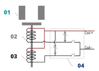
Coil Control Circuit Diagram
Single coil, without auxiliary contact Single coil, with auxiliary contact

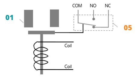
Dual coil, without auxiliary contact Dual coil, with auxiliary contact
![]()
 Coil and Auxiliary Output
Durakool typically provides buyers with standard coil (and auxiliary, if selected) wire length DC contactors - without connectors.
We also offer customisation, including the length of coil leads, different insulation sleeve materials, length of auxiliary leads, insulating sleeves, quick-connect terminals and labelling.
When purchasing Durakool DC contactors, please contact our team with your specific custom requirement.
Instructions for Use
Load
Applications with capacitors (C load) will require a pre-charge circuit (refer to Fig. 1), otherwise, it may cause power contacts welding.
 Fig. 1
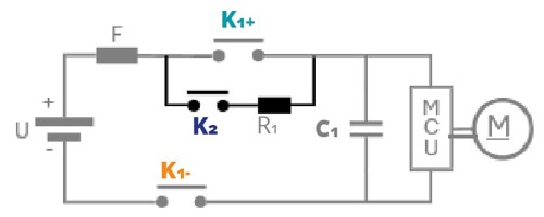
'Dry' (no load ) switching cycles should be applied to the contactor before use, to optimise contact resistance, by mechanically cleaning / polishing the surface of the contacts. This is recommended for ALL contactors.
Electrical Life
The rating is based on resistive load (L/R ≤ 0.1ms). Your application may be different, therefore, we suggest you test the DC contactor in your circuit, to verify life is as required.
End of life is defined as when the dielectric, insulation resistance or contact resistance exceeds the specifications listed.
- DC contactor is a high-voltage DC switch. At the end of its life, it may lose its normal operating capability. Therefore, do not exceed the standard switching capacity and number of life cycles. Treat the DC contactor as a product with a limited life span and replace it when necessary.
Mounting
 GapsInstallation of a Durakool DC Contactor should always be undertaken by a competent person, with sufficient knowledge of DC safe working practices.
- All surfaces should be free of surface contamination. Oils and greases and protection materials should be removed before the connection process commences, to avoid additional heat generation.
 Mounting HolesAlways use the washers provided (if included), to prevent the screws from loosening. Connection systems should be tightened to the locking torque as specified. Over torquing the product can lead to premature life failure.
- Ensure there is no gap between the conductors and the power contact terminal. A gap will cause the power contacts to abnormally overheat.
- Conductor mounting holes should be sufficiently sized to ensure a tight fit. With this in mind, the contact surface area, between the conductor and power contact terminal should be as large as possible.
- The dual coil and PWM coil leads are polarised (see 'Coil control circuit diagrams').
- Please connect the coils according to the standard.
- Incorrect cable polarity can result in contactor pick-up failure and may damage the contactor.
- Thread locker should not be used.
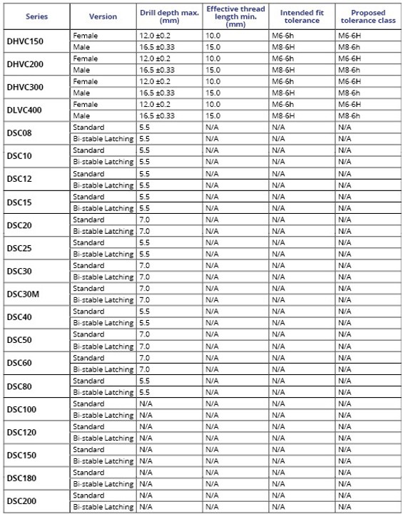
Please refer to Stud Information Tables below:
Stud Information Table 1
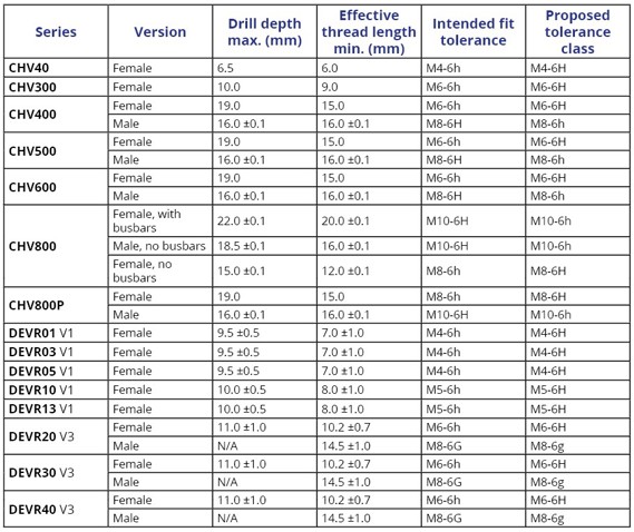
Stud Information Table 2
Temperature Rise of Power Contacts and Cable Sizing
- Cables should always be sized in accordance with global, country or local state normative harmonised standards as a minimum. However, to maintain performance across the full working specification range, please refer to details of the datasheet.
- During normal DC contactor operation, the operating temperature of the contacts needs to be maintained. Follow recommendations specified within the product's datasheet to avoid exceeding maximum allowable temperatures.
- Good ventilation or other active cooling methods should be maintained to ensure effective cooling of the DC contactor. The DC contactor has high current carrying capability, which may generate a large amount of heat. The buyer needs to take sufficient measures to minimise heat generation and use effective cooling methods.
Storage
For silver plated products, such as the DEVR series, discolouration of the power terminals may occur, unless stored in the following optimal condition:
- Ambient temperature between 20⁰C - 26⁰C.
- Relative humidity between 30% - 60%.
- Avoid storing together with acidic or alkaline substances.
If there is discolouration on the terminals for any reason, it is highly likely not to affect the mechanical or electrical performance of the product.
For other products, please refer to details of the datasheet for specific information.
Other
- All performance data listed in the datasheet are initial values tested under standard testing conditions.
- Please avoid impact or dropping of the DC contactor during application or transportation. To maintain the performance of the DC contactor, it is not recommended to continue using the DC contactor after impact or fall.
- Please avoid installation in a strong magnetic field (around the coil or the magnets) and of heating objects nearby.
- The driving circuit power of the DC contactor coil needs to be sufficient to drive the contactor coil, otherwise it will reduce the breaking capacity of the DC contactor. Please refer to details of the specific product's datasheet.
Statement
- Durakool product specifications are only relevant to Durakool products, used to connect the designer ('buyers'). The buyer understands and agrees that the buyer is still required to conduct adequate testing and evaluation of the Durakool product itself, when designing its system or product, to determine whether the Durakool product is suitable for the buyer's system or product.
- The data in the Durakool product specification sheet is based on standard laboratory conditions and engineering practices. Any discrepancy in the data found by the buyer when evaluating a Durakool product may be the result of different test conditions. Buyers can contact Durakool for technical support.
- In the search of continuous improvement and product evolution, Durakool reserves the right to update its standard product range and may make changes to product specifications without notice. Buyers may contact Durakool or visit the website for the latest product specifications.
This user manual is subject to change without notice. E&OE.