
- Home
- Products
- Information
- Catalogues
- Datasheets
- Product Videos
-
Technology
- Whitepaper Powering Success
- Browse Technologies
- Blowout Magnets - What They Are & Why Use Them
- Contact Resistance Versus Pressure
- Contacts Construction & Materials
- EV Battery Charging Applications - Relays & Contactors
- How to Avoid Common Relay Problems
- HVDC Contactors & Failure Modes
- HVDC Relays & Contactors Conductor Size & Heat Dissipation
- HVDC Relays & Contactors Overview
- Latching Relays
- Layman's Guide to Coil Suppression
- Relay Contact Forms - An Explanation
- Switching Polarised & Non Polarised
- Temperature effects - EMR Operation
- Applications
- About us
- News & Events
-
Latest News
- All our Latest News
- iVT Expo Germany reflections
- Custom or Standard?
- The Relay - More than just a simple black box
- ACT Expo 2025
- Enhancing energy efficiency in contactors and relays for mobile applications
- Navigating market dynamics: a power control industry perspective
- Forklift Revolution - Keeping you informed
- Durakool Distributor Conference
- Enhancing Energy Efficiency in Modern Electrical Systems
- Durakool at Detroit Battery Show 2024
- Unveiling relay solutions for EV and industrial applications
- Ensure Your Forklift Relays Don't Fail - Learn How!
- iVT Cologne - Electrification
- Absolutely worth the visit
- Istanbul EV Charge
- Engineering & Design Show 2023 - Excellent Show
- Durakool in Gothenburg
- HVDC Range Expansion 2023
- Product launch at Stuttgart Battery Show 2023
- Teamwork Appreciation - Las Vegas
- Durakool in the Fast Lane at Silverstone
- Valuable time spent with our customers
- Intro Durakool Pre-Charge & Discharge Resistors
- Great Success 2022 Battery Show
- Socking it to you!
- Dig Yourself Out of a Hole
- Keep Your Cool at the Wheel
- Need a Socket to Go with That Relay?
- Events
-
Press Releases
- All our Latest Press Releases
- Breakthrough DLVC200 and DLVC300 contactors from Durakool boost performance and reliability
- Durakool launches new high-performance DG86M relay
- Durakool unveils first-of-kind relay solution for electric vehicle and industrial applications
- Optimised, safe & reliable solutions from Durakool - iVT Expo
- Durakool Announces Expansion of High Voltage DC Portfolio
- Durakool Announces High Voltage DC Switching Contactors for Superior Isolation, Improved Reliability and Longer Service Life
- AUTOMOTIVE HIGH VOLTAGE - TWO IN ONE!
- An Easier and Safer Life with the Unique DG55M
- Move Up in the World with DG38L PCB Motor Control Relays
-
Latest News
- Contact us
- Portal
Blowout Magnets - What They Are & Why Use Them?
The rise in demand for electric vehicles, together with introduction Lithium based batteries and the popularity of alternative energy sources such as photovoltaic (solar) panels has led to increased requirements to switch ever higher DC voltages. For example, the domestic car once used 6VDC batteries (in the 1950’s) and this increased to 12VDC and 24VDC in trucks. Now, 48VDC (mild hybrid) systems are in relatively common use in cars and commercial vehicles. Hybrids and pure EV’s are now working with 400VDC and even as much as 1000VDC. Many smaller vehicles, such as forklift trucks, that once used 24VDC or 48VDC are using 72VDC or higher battery voltages.
But this is not new, there were electric cars before internal combustion engine cars and there were DC motored electric railway locomotives pre-1900. In fact, up until Henry Ford introduced the Model T, electric cars were more common than IC engine vehicles in the USA.
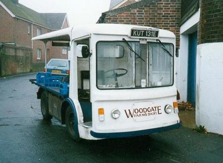 In the UK, the “electric milk float” was once a common sight at night delivering milk bottles to doorsteps throughout the land. But these were all lead acid battery-based vehicles and PV panels were yet to be invented.
The one big problem facing anyone switching a high current DC load is how to turn off the arc which is generated when the switching contacts open. By comparison, switching AC is easy, the arc is self-extinguishing every time the waveform crosses zero which happens several times, depending on the AC frequency, whilst the contacts open and move apart.
For a DC load, the only way to turn the switching arc off is to have a contact gap big enough that the arc eventually goes out as it cannot sustain itself. This requires a big device to do the switching (big gaps require distance and therefore big coils to move contacts long distances). So, over time, a number of techniques have been developed to safely extinguish the DC switching arc. One of the earliest ideas was to use a magnet to extend the arc distance (or “blow out” the arc). The magnet could be a fixed magnet or an electro-magnet and is still in use today. This technique enables a smaller DC relay or contactor than otherwise would be possible. What has changed is that companies like Durakool, who have a long history in DC switching technology, are using magnets in ever smaller relays to extend the relay’s DC switching capability as well as in new, special, contactors to switch higher voltages up to 1000VDC or more.
So, how does the magnet work? Most electrical engineers are familiar with Fleming’s 'Right-Hand Rule' which determines the direction in which a current will flow when a conductor moves through a magnetic field. It is the basis for generators, but it’s corollary is Fleming’s 'Left-Hand Rule' which determines the direction of movement of a conductor if a magnetic field is applied across the conductor. This is the rule we need!
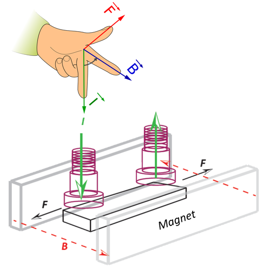 The switching arc is the conductor with a current flowing through it with the actual medium being the plasma between the opening contacts; and the magnetic field is applied from external magnet(s). These magnets are positioned to deflect the arc away from the opening contacts and as a result, stretch the apparent contact gap to the point I where the arc is no longer self-sustaining and goes out. In the diagram (left) the arcs are deflected outwards (F).
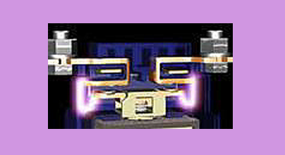
The photo (below) shows the arcs being stretched before being extinguished in a HVDC contactor.
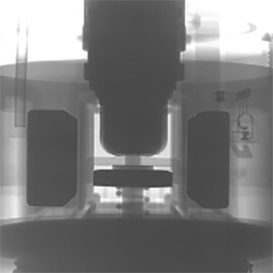
The X-ray photograph (right) shows an end on view of the contacts for the Durakool DEVR60 HVDC contactor. The magnets can be clearly seen either side of the moving contact bar. Comparison with the line drawing above makes it obvious.
 The main disadvantage of using magnets for arc quenching is that it polarises the relay or contactor’s terminals – the current must flow in the correct direction for the magnetic field of the magnets to deflect the switching arc in the correct direction. If the current flows in the reverse direction, the arc will be deflected incorrectly which might lead to failure of the relay or contactor, or, at the very least, reduced switching life. You can see in the example above that if the current flows in the opposite direction, the arcs will be deflected inwards and might not be extinguished, or, stay in place long enough to damage the contact surface.
The examples so far show magnets in contactors which have a double break configuration as standard. With relays there is usually, but not always, only a single fixed contact and a single moving contact. Here there is usually enough space to fix only one magnet and, due to the reduced size, care must be taken that the magnetic field does not interfere with the coil operation, whilst also ensuring that the arc is deflected in a safe direction.
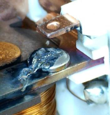
In the photo (left) can be seen what might happen if the magnet orientation is incorrect. In this example, the arc has been directed, by the magnet, up the contact blade instead of at 90’ to the blade. The result is that the contact has melted because the arc was not extinguished quickly. This was after only 250 operations.
Durakool’s DEVR range of HVDC contactors all contain magnets for arc quenching, as do Durakool’s DG17M, DG55M, DG57BM, DG57CM & DG85CM automotive relays, together with the DG38L industrial relays. Magnet blowouts are also available as an option in the Durakool DSC series of LVDC contactors.
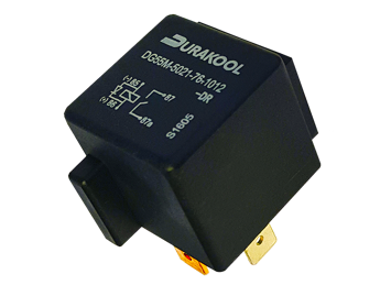
Pictured (left) is the Durakool DG55M relay. The magnet position can be seen on the side of the relay which can switch 80VDC, or more, at up to 20A in a standard Mini-ISO style automotive relay.
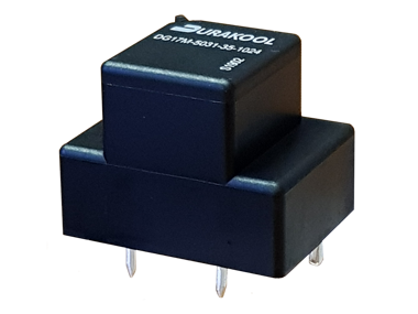 The Durakool DG17M relay (right) is one of the smallest relays available capable of switching up to 450VDC. It is only 25 x 19 x 19.5mm!
In conclusion, magnets are a well-established method for extending the DC switching capabilities of relays and contactors by directing (or blowing out) the DC arc away from the contacts as they open.
Modern manufacturing techniques, new materials and innovative designs mean that magnets are finding new niches in ever smaller relays and contactors whilst, at the same time, extending those same relays and contactors’ abilities to switch higher DC voltages and currents.