
- Home
- Products
- Information
- Catalogues
- Datasheets
- Product Videos
-
Technology
- Whitepaper Powering Success
- Browse Technologies
- Blowout Magnets - What They Are & Why Use Them
- Contact Resistance Versus Pressure
- Contacts Construction & Materials
- EV Battery Charging Applications - Relays & Contactors
- How to Avoid Common Relay Problems
- HVDC Contactors & Failure Modes
- HVDC Relays & Contactors Conductor Size & Heat Dissipation
- HVDC Relays & Contactors Overview
- Latching Relays
- Layman's Guide to Coil Suppression
- Relay Contact Forms - An Explanation
- Switching Polarised & Non Polarised
- Temperature effects - EMR Operation
- Applications
- About us
- News & Events
-
Latest News
- All our Latest News
- iVT Expo Germany reflections
- Custom or Standard?
- The Relay - More than just a simple black box
- ACT Expo 2025
- Enhancing energy efficiency in contactors and relays for mobile applications
- Navigating market dynamics: a power control industry perspective
- Forklift Revolution - Keeping you informed
- Durakool Distributor Conference
- Enhancing Energy Efficiency in Modern Electrical Systems
- Durakool at Detroit Battery Show 2024
- Unveiling relay solutions for EV and industrial applications
- Ensure Your Forklift Relays Don't Fail - Learn How!
- iVT Cologne - Electrification
- Absolutely worth the visit
- Istanbul EV Charge
- Engineering & Design Show 2023 - Excellent Show
- Durakool in Gothenburg
- HVDC Range Expansion 2023
- Product launch at Stuttgart Battery Show 2023
- Teamwork Appreciation - Las Vegas
- Durakool in the Fast Lane at Silverstone
- Valuable time spent with our customers
- Intro Durakool Pre-Charge & Discharge Resistors
- Great Success 2022 Battery Show
- Socking it to you!
- Dig Yourself Out of a Hole
- Keep Your Cool at the Wheel
- Need a Socket to Go with That Relay?
- Events
-
Press Releases
- All our Latest Press Releases
- Breakthrough DLVC200 and DLVC300 contactors from Durakool boost performance and reliability
- Durakool launches new high-performance DG86M relay
- Durakool unveils first-of-kind relay solution for electric vehicle and industrial applications
- Optimised, safe & reliable solutions from Durakool - iVT Expo
- Durakool Announces Expansion of High Voltage DC Portfolio
- Durakool Announces High Voltage DC Switching Contactors for Superior Isolation, Improved Reliability and Longer Service Life
- AUTOMOTIVE HIGH VOLTAGE - TWO IN ONE!
- An Easier and Safer Life with the Unique DG55M
- Move Up in the World with DG38L PCB Motor Control Relays
-
Latest News
- Contact us
- Portal
Durakool Latching Relays
A latching relay or contactor is an electro-mechanical relay (or contactor) with contacts that are stable in two positions without voltage applied to the coil – hence the other common name of “Bi-stable Relay”. Voltage is applied to the coil only to enable the contacts to change state – the coil does not have to be energised for the contacts to stay in either position.
The most common type of electro-mechanical relay is “monostable” i.e., it is only stable in one position – when the coil is not energised; and held in the second position only when the coil is energised. It automatically returns to the at-rest state when the coil is de-energised.
There are three commonly encountered techniques for making a latching/bi-stable relay.
Firstly, there is mechanical latching with a similar mechanism as encountered in a ball point pen. One pulse makes the contacts move from the first position to the second position and a second pulse of the same polarity makes the contacts return to the initial position. This type is rarely seen in small relays and contactors and is usually reserved for specialist devices. Durakool does not have any latching relays or contactors which use this type of mechanism.
Secondly, there are remanence relays which rely on a magnetic field to hold the contacts in the operated position. This type is often found in small PCB relays and is frequently a modified version of a standard monostable type. There are two different types, single coil and twin coil.
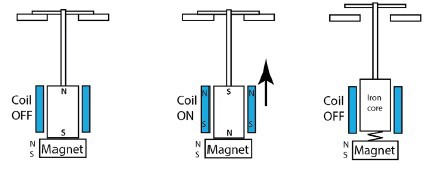
Finally, there is the magnetic latching type of relay which relies on a moving armature which contains a magnet, and that pivots around a central point through a short arc. The armature looks like the letter “H” and so this type is sometimes referred to as a H armature latching relay. Latching/bi-stable contactors use a different type of magnetic latch. Latching
Contactors have a permanent magnet which holds the moving “plunger” in the latched state. The magnetic circuit is finely balanced so that when the coil is energised, the magnetic field generated in the plunger is attracted to the magnet (opposite poles attract). When the latching voltage is removed from the coil, the plunger is held in the operated (SET) state by the magnet. To reset the contacts, a voltage of the opposite polarity is applied to the coil. This generates a magnetic field with the same polarity as the magnet and the plunger is pushed away from the magnet by the opposing magnetic fields. There is usually a return spring to assist the initial separation and to keep the contacts from closing.
The common feature of all four types is that they require no energy to hold the contacts in either of the two states. The only time voltage needs to be applied to the coil(s) is when the contacts are required to change state and for long enough for the contacts to have come to rest and, in types 2 & 3, a stable magnetic field to become established. This makes bi-stable relays ideal for energy conscious applications or where a “memory” function might be required in the event of a power failure. A typical application is a pre-paid electricity meter.
Remanence relays
Looking a bit more deeply at the remanence relays, it will have been noted that there are two types, one with a single coil and the other with a twin coil. The remanence relay relies on a special iron core that retains its magnetism after the coil has been de-energised.
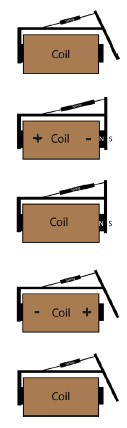
- When the coil is energised, the contacts move against a return spring, just like a monostable relay, but the retained magnetism in the core holds the contacts in the operated (SET) position against this spring, even though the coil is no longer energised.
- When the coil is operated with a reverse polarity to the SET polarity, the magnetic field in the core is erased and the contacts return to the initial (RESET) position.
However, care must be taken that the RESET voltage is lower than the SET voltage or it’s possible that the magnetic field in the core could be established with the opposite polarity and the contacts bounce back into the SET position. The usual way to counter this with twin coil types is to have slightly different coil windings for the SET and RESET coils. That way the operation is transparent for the user. Single coil types though sometimes require more care. Here the relay requires a SET pulse in one polarity and a RESET pulse of a lower voltage in the opposite polarity.
One of the disadvantages of the remanence relay is that it relies on the strength of the magnet field in the core to hold the relay in the operated (SET) position. This makes it vulnerable to shock and vibration. A strong shock in the right direction could cause the contacts to change state.
H Armature relay
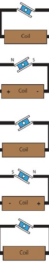 The “H” armature relay contains an armature which pivots between the ends of an extended core piece which has been formed into a “C” shape. Energising the coil in the SET direction causes the magnet in the H armature to be attracted to the end of the C shape. Energising the coil in the opposite direction reverses the magnetic field in the C with the effect that the H armature flips over to the other end. Essentially the armature pivots through an arc of about 90° or less. Reference to the diagrams will make this clearer.
The twin coil version has a coil with a centre tap. The centre connection is the common terminal and energising either the SET coil or the RESET coil will cause the contacts to move to the respective position. Note that both coils must not be energised at the same time or damage to the coil might occur. The single coil version just requires the polarity to be reversed through the coil to make the contacts change state.
It is possible with Durakool twin coil types to use them as a single coil type by ignoring the centre common connection.
The H armature latch relay is less susceptible to shock and vibration than the remanence type as the magnet in the armature holds the contacts in the operated state at both ends of the C shaped core.
Although rare, it is possible to find monostable (non latching relays) that use the “H” armature principle. These use a combination of a weak (or non-existent) magnet in the “H” and a return spring which returns the armature and the contacts to the start position as soon as the coil is de-energised.
Before we look at the latching relays in the Durakool range, it is worth considering another alternative and that is to electronically latch a relay. This method uses a double pole relay where one set of contacts is in parallel with the operating switch and supplies current to the coil once the contact is closed. To RESET the relay a normally closed switch is inset into the circuit such that it breaks the supply to the coil through the second contact set causing the coil to de-energise. Of course, this circuit relies on there being a constant voltage applied to the whole circuit – if that voltage fails the relay will RESET automatically as the coil is de-energised. There is no “memory” of the state of the contacts which occurs with a true latching relay.
This “memory” after power fail is one of the benefits of latching relays, but also one of the problems. It is of benefit where energy saving is required as the latching relay requires no energy to keep it in the operated (SET) state and only a short pulse is needed to make it change state. So, that makes it ideal for applications such as electricity meters, or battery-operated devices, where the relay will stay in the operated position for a very long time and consume no current whilst doing so.
On the other hand, the “memory” effect where the contacts maintain their status after power fail can be a problem. When the power returns, it’s not obvious in what state the contacts are – they will be in the state they were in before power fail, but if there is no record of that status then a problem could occur. In this situation, a monostable relay is advantageous as it’s known that the contacts will automatically RESET as the coil de-energises with the power fail.
One way around the problem of the “memory” effect is to use a circuit that retains just enough energy after power fail to set the contacts into a known position. For example, a RESET pulse is sent after power fail is detected, if the contacts are already in the RESET position, they will stay unmoved, but if they are in the SET state the contacts will revert to the RESET status. This requires a few additional circuit components to hold up the supply for long enough for a pulse to be supplied to the coil.
Another way to take care of this situation is to use a latching relay with an auxiliary contact which mirrors the power contact(s). Checking the status of this contact will show the status of the power contact(s) and action can be taken to correct the contact status before power is applied to the main contact(s).
It is possible to design an electronic circuit incorporating a latching relay that acts like a monostable (non-latching) relay. See Appendix 1 for further details.
Latching contactors
Latching contactors work in a different way to relays and usually contain a fixed magnet which holds the contacts in the operated state. As in all things, there are variations and other ways of doing it!
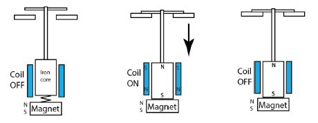
The latching contactor consists of a plunger connected to the contacts which, like a monostable contactor, is pulled down into the coil. But, unlike a monostable contactor, there is a magnet which holds the plunger down. A spring is positioned in such a manner, here shown between the plunger and the magnet for simplicity but more likely not in that position in reality, keeps the plunger from dropping into the coil when not required.
When the coil is energised, it induces a magnetic field in the plunger and the plunger is drawn down towards the magnet and the contacts close. When the coil is de-energised the magnet holds the plunger down in the SET position and the contacts remain closed.
When the coil is energised with reverse polarity, the magnetic field in the plunger is reversed and the two magnetic fields oppose each other and, assisted by the spring, the plunger moves up and the contacts open (RESET).
A similar process occurs with twin coil latching contactors except that one coil is used to SET the contactor and the other coil is used to RESET the contactor.
Applications
Most applications for latching relays are for energy saving in one form or another, especially where the relay or contactor might be required to stay in the operated position for long periods of time. A latching relay will draw no power whilst in the SET state which has the dual advantage of saving energy and reducing possible heating from the relay coil. The “memory” function might also be of use, for example in an electricity smart meter where in normal use the relay remains in the SET condition for most of its life, but if required the utility provider can remotely access the relay and RESET it to disconnect the power to the property. In a similar vein, hotel rooms can be “powered down” when not in use as an energy saving exercise.
Battery operated devices can also benefit from the zero power consumption when in the SET position. Latching relays can even be used in battery management systems to disconnect the battery when not in use or to prevent batteries being dangerously discharged. The relay disconnects the battery before the battery is damaged and prevents further use until a charging circuit resets the relay. As a further measure, the product in which the battery is mounted could contain no internal way to reset the relay, only plugging in the charger with a separate supply to the reset coil will allow the latched relay to RESET.
Modern microprocessors and integrated circuits make logic circuits very easy to implement, but latching relays together with monostable relays can be used to make simple and complex logic circuits. See Appendix 2 for an example.
Durakool Latching Relays and Contactors
 Durakool has range of power latching relays, mostly of the “H” armature type, including two that are as small as some PCB remanence power relays, together with two small signal relays and a full range of latching low voltage DC contactors able to carry as much as 2000A.
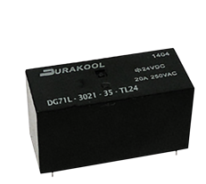
The DG70 and DG71 types fit the industry standard 16A PCB power relay footprint such as the Durakool DM85 type. But the twin coil type has an extra coil pin between the normal coil pins compared to the DM85. This is similar to some remanence latching relays from other suppliers except the Durakool relays employ the “H” armature design.
Designed for smart meter applications, the Durakool DG79B can carry up to 120A and meets the UC3 requirements for electricity metering. The DG76C is smaller and PCB mounting but can still switch 90A and is finding applications for low voltage battery disconnection in small EV’s such as scooters. Most of the DG7* series of latching relays can be heavily customised to suit the application including addition of current transformers or current shunts and linking multiple relays together.
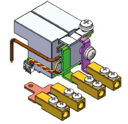
Custom DG79B assembly
The Durakool range also includes latching relays with potential applications in electric vehicles and “green energy” such as battery storage or solar power generation.
 The DX71D, DX71E and DX71F are designed for PCB mounting, DC switching up to 80VDC and currents as high as 125A, they also feature an auxiliary contact to monitor the position of the power contact.
Also featuring an optional auxiliary contact, the Durakool DSC series of DC contactors include latching versions with up to 2000A switching capability (DSC200). This is a big contactor weighing upwards of 4kgs! The latch function enables the contactor to be in the SET period for long periods without undue wasted energy or heating.
Appendix 1
It is possible to design an electronic circuit incorporating a latching relay that acts like a monostable (non-latching) relay. This has the advantage that the circuit consumes little or no power whilst the circuit is energised unlike a monostable relay and that it will return automatically to the start position when the power is removed from the circuit. The disadvantage is that it needs more components and there is the risk, however small, that in the event of a component failure in the drive circuit, the latching relay will not return to the initial start position.
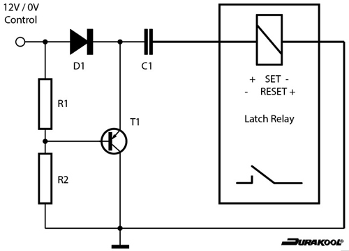
This type of circuit is more suited to smaller latching relays as the components needed for bigger relays and contactors necessarily get larger too. An example of this circuit is shown on the next page. The actual component values will need to be selected with reference to the coil data of the latching relay chosen.
With a 12VDC input, C1 is charged and there is a brief current through the relay coil as the capacitor starts to charge. The relay changes state and the current is limited to the level, determined by R2. When the input voltage drops suddenly to 0V, the capacitor discharges via the relay coil with a reverse current and the relay resets.
Obviously, the above circuit is just a simple schematic, and relies on clearly defined voltages but it could be modified to include a Schmitt Trigger to cope with slower rising or falling control voltages and further modified to add additional options as required.
Appendix 2
Imagine an application where there is only available a 12VDC supply and a momentary action push button switch which is limited in the amount of current it can switch. How could you design a circuit where a single push of the switch turns the 12VDC power to the load on, and a second push of the same switch turns it off again? Whilst the load circuit is on there is no supply to the control circuit except when the push button switch is pushed. The circuit below shows how this might be accomplished using only relay logic. This is an example of a real application!
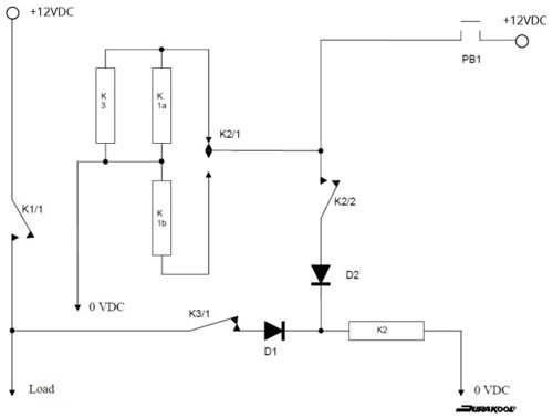
K1 is a twin coil, SPST, latching relay. K2 is a small DPDT relay and K3 is a small SPDT relay using the normally closed contact. K3 only has to switch the coil of K2 so can be a small signal type relay. K2 needs to chosen to suit the coil of K1. If K1 is a PCB relay then K2 could also be a signal relay but the load is inductive and care must be taken to ensure that K2’s contacts can cope with the inrush currents from K1’s coils, especially if K1 is a larger relay or contactor. K1 will need to be chosen to ensure that its power contact can switch the desired load.
The diodes are not too important as they are simple blocking diodes but need to be able to carry K2’s coil current. Some thing as basic as a 1N4001 would be OK.
In this application, the push button switch is a SPST-NO type with momentary action (i.e. push to make, non latching) with just enough capability to handle K1’s coil inrush. For a pcb relay, any small push button switch is suitable as it only needs to switch less than 100 milliamps (e.g. Durakool DG71 = <85mA at 12VDC).
How does the circuit work? There is a lot going on!
When PB1 is pressed 12VDC is applied to K1a (one of the twin coils of K1) and to the coil of K3. Contact K1/1 closes (SETS) and power is applied to the load. At the same time K3/1 opens isolating K2.
When PB1 is released, K3 drops out closing K3/1 and applying 12VDC (from the load circuit via K1/1) to K2’s coil. K1 stays as it was set as its a latching relay. K2/1 changes state and connects K1b to the push button ready to activate when PB1 is pushed next. K2/2 closes and connects the push button to K2 coil. The purpose of K2/2 is revealed later!
Now the load is ON via K1/1 and only a small amount of current is being drawn via K3/1 and K2. When the PB1 is pressed for the second time, K1b is connected to 12VDC via K2/1 (now in the operated position) and K1/1 opens (RESETS) and disconnects the load. K2 would drop out immediately K1/1 opens but K2/2 remains closed whilst PB1 is pressed holding K2 operated. As soon as PB1 is released, K2 drops out, K2/2 opens and K2/1 changes back to its original status ready to start the whole process again. No current is being drawn and the system is ready to operate again. It is a complicated way to do it and timings may have to be adjusted to account for the different operating speeds of the relays, an extra diode might be all that is needed. The main problem is ensuring that the push button switch is operated for long enough for the circuit to SET or RESET.