- Home
- Products
- Information
- Catalogues
- Datasheets
- Product Videos
-
Technology
- Whitepaper Powering Success
- Browse Technologies
- Blowout Magnets - What They Are & Why Use Them
- Contact Resistance Versus Pressure
- Contacts Construction & Materials
- EV Battery Charging Applications - Relays & Contactors
- How to Avoid Common Relay Problems
- HVDC Contactors & Failure Modes
- HVDC Relays & Contactors Conductor Size & Heat Dissipation
- HVDC Relays & Contactors Overview
- Latching Relays
- Layman's Guide to Coil Suppression
- Relay Contact Forms - An Explanation
- Switching Polarised & Non Polarised
- Temperature effects - EMR Operation
- Applications
- About us
- News & Events
-
Latest News
- All our Latest News
- iVT Expo Germany reflections
- Custom or Standard?
- The Relay - More than just a simple black box
- ACT Expo 2025
- Enhancing energy efficiency in contactors and relays for mobile applications
- Navigating market dynamics: a power control industry perspective
- Forklift Revolution - Keeping you informed
- Durakool Distributor Conference
- Enhancing Energy Efficiency in Modern Electrical Systems
- Durakool at Detroit Battery Show 2024
- Unveiling relay solutions for EV and industrial applications
- Ensure Your Forklift Relays Don't Fail - Learn How!
- iVT Cologne - Electrification
- Absolutely worth the visit
- Istanbul EV Charge
- Engineering & Design Show 2023 - Excellent Show
- Durakool in Gothenburg
- HVDC Range Expansion 2023
- Product launch at Stuttgart Battery Show 2023
- Teamwork Appreciation - Las Vegas
- Durakool in the Fast Lane at Silverstone
- Valuable time spent with our customers
- Intro Durakool Pre-Charge & Discharge Resistors
- Great Success 2022 Battery Show
- Socking it to you!
- Dig Yourself Out of a Hole
- Keep Your Cool at the Wheel
- Need a Socket to Go with That Relay?
- Events
-
Press Releases
- All our Latest Press Releases
- Breakthrough DLVC200 and DLVC300 contactors from Durakool boost performance and reliability
- Durakool launches new high-performance DG86M relay
- Durakool unveils first-of-kind relay solution for electric vehicle and industrial applications
- Optimised, safe & reliable solutions from Durakool - iVT Expo
- Durakool Announces Expansion of High Voltage DC Portfolio
- Durakool Announces High Voltage DC Switching Contactors for Superior Isolation, Improved Reliability and Longer Service Life
- AUTOMOTIVE HIGH VOLTAGE - TWO IN ONE!
- An Easier and Safer Life with the Unique DG55M
- Move Up in the World with DG38L PCB Motor Control Relays
-
Latest News
- Contact us
- Portal
EV Battery Charging Applications - Relays & Contactors
Introduction to relays and contactors for EV charging applications

Electric vehicles, in one form or another, have been around for over 100 years. Early vehicles used lead acid batteries and worked at 6V and upwards. Lead acid EV’s are still around in the 21st century in large numbers (think forklift trucks or golf carts, for example) but Lithium based batteries are replacing them, especially in applications such as cars, vans and trucks.
The basic lead acid battery charger consists of an AC to DC converter and some, often simple, circuitry to control the charging voltage and current to a level suitable for the battery configuration. Batteries may be connected in parallel (more current) and in series (higher voltage) to get the required performance from the electric motor(s) used to propel the vehicle. Typically, battery voltages for lead acid batteries are 12VDC, 24VDC, 36VDC and 48VDC. A basic cable with connectors is used to connect the charger to the vehicle. The traditional lead acid battery charger itself was (and still is) a generous, heavy, piece of equipment that may be “hard wired” into the domestic single-phase supply or to an industrial three phase supply. Modern technology has enabled much smaller domestic “trickle” chargers used to maintain charge on a vehicle battery whilst the vehicle is not being used.
The advent of Lithium battery-based vehicles led to battery voltages increasing to 400VDC or 800VDC,and even 1200VDC, to increase power whilst keeping weight as low as possible. (Higher voltages = lower current and therefore lighter conductors.) But, charging via a domestic AC socket to an onboard AC/DC charger is slow. Charging time can be reduced using DC Fast Chargers, which supply high voltage DC direct to the vehicles’ battery systems, bypassing the onboard AC/DC converter. However, these require a 3-phase AC supply and are not suitable for domestic installations.
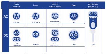
Initially, there was very little cable and connector standardisation, but this needed to change to allow vehicles to charge on the various different chargers they might encounter on a journey away from home. Now we have a set of international standards, but even these are subject to change and revision as the market grows, and there are still differing standards between continents for the plug and socket layouts. It is a fast-changing market with new innovations arriving daily.
One thing remains common to all chargers though, the requirement for safety. AC supplies to the vehicle, single phase or three phase, are dangerous voltages if something should go wrong or the cable be disconnected accidentally or maliciously (theft of the cable for example). The same is also very true of DC supplies, especially high voltage DC, there is a real risk of death by electrocution, or fire, if protective measures are not put in place.
Types of Electric Vehicle Chargers
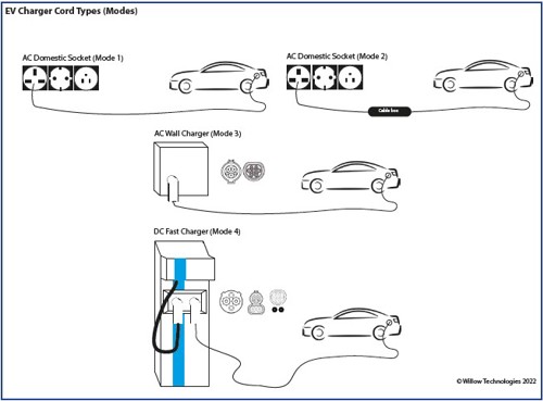
| AC SAE J1772 Level 1 | AC SAE J1772 Level 2 & Level 3 | DC Fast Charger |
| Basic Home Installation | Advanced Home & Public Installations | Public & Commercial Installations |
| IEC 61851-1 Mode 1 or Mode 2 | IEC 61851-1 Mode 3 | IEC 61851-1 Mode 4 |
| Voltage 120VAC, 1 Phase 240VAC, 1 Phase 480VAC, 3 Phase |
Voltage 208-240VAC, 1 Phase 250VAC, 1 Phase 480VAC, 3 Phase |
Voltage In 380V-600VAC, 3 Phase Voltage Out 400VDC to 800VDC |
| Current rating (AC) 12A to 16A, 1 Phase 32A, 3 Phase |
Current rating (AC) 12A to 80A |
Current rating Out (DC) 400A (or more) |
| Charging time Approx. 8 to 12 hours* |
Charging time Approx. 4 to 6 hours* |
Charging time 15 to 30 mins** |
| * Vehicle battery dependent | ** to 80% charge and vehicle | |
In all these chargers, excluding the very simple cable to a domestic socket (Level 1), there is some form of communication between the vehicle and the charger over the charging cable, the cable arrangement being defined by standard. The simple cable to domestic socket will usually have a small control box in the cable itself (Mode 2). Cables without a control box are banned in some countries. Unfortunately, there are several competing standards for cables and connectors, so which one is correct for the vehicle will likely depend on the geographical area in which the vehicle is situated as well as the design of the onboard AC/DC charger, or the DC charging control system.
Relays and Contactors for AC Systems (Modes 2 & 3)
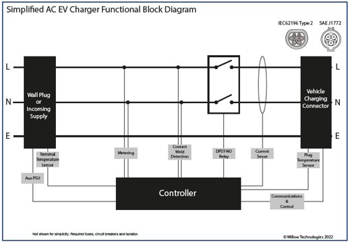
Relays and contactors are used to disconnect the cable, or cable socket, from the vehicle in the event of a problem, or at the end of a complete charge cycle. They must be able to break the full AC current to the onboard charger under load in an emergency, but would normally be switching under no, or very little, load current. For this application, traditional AC contactors will suffice, but they are bulky and relatively difficult to package into a small wall mounted enclosure, as is the usual practice for domestic charger installations for electric cars.
Usually, electric cars come with a cable with a domestic plug at one end and a SAE1772, or equivalent, plug at the other which enables the onboard charger to be used. There is a control box integrated in the cable for safety functions (Mode 2). Cables without a control box (Mode 1) are forbidden in certain countries for safety reasons, there being no way to disconnect the vehicle from the socket in the event of an onboard problem. Traditional AC contactors are not suitable for use in the control boxes integrated into the charging cable due to their size, but also due to the potential for shock damage to the contactor, or inadvertent operation, when the cable is dropped.
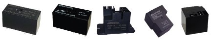
PCB mounted relays are ideal for these applications, being smaller and less susceptible to inadvertent operation caused by shock. Domestic systems are usually limited to around 32A. Typically, the requirement is to break both the Live and Neutral for safety and therefore a double pole relay, such as the Durakool DE35, is ideal for this.
Mode 3, or Level 2, wall mounted chargers can supply more current, up to 80A in 3-Phase commercial systems, so larger relays are required. Like the Mode 2 Chargers, the requirement is to break both the Live and Neutral for safety and therefore a double pole relay, such as the Durakool DE35, is also ideal for this. The Durakool DE35 is rated at 40A/277VAC switching per pole and is only 49 x 26.5 x 30mm. With both poles in parallel the DE35 can carry 72A, so two would be required for the higher current systems, one for Live and one for Neutral. The Durakool DE35 features contact sets that are mechanically linked ensuring that Live and Neutral are broken simultaneously.
It is also possible to use two or more single pole relays, such as the Durakool DG34 or DG38 series, with one relay switching Live and another switching Neutral where the current is limited to 40A. Whilst not ideal, this method does have the advantage that the PCB layout can be more flexible. The disadvantage is that if one relay should weld closed, or fail, the other will still operate.
Relays and Contactors for HVDC Fast Chargers
DC Fast Chargers (Mode 4) convert the incoming 3-Phase supply to high voltage DC to charge the onboard batteries directly, bypassing the onboard AC/DC charger. This is much quicker, but the voltages and currents are much higher too. The voltage supplied to the battery is DC, which brings its own problems when it comes to switching. Typically, the DC voltage will be 400VDC or 800VDC with very high currents, maybe 400A or even more. These are extremely dangerous voltages and currents, with a real risk of death by electrocution if a person should come into contact. In addition, should something go wrong, for example a battery short circuit, the resulting currents in the charging cables could be as high as 3000A or more. In these circumstances the charger must be able break the load current to avoid the risk of fire, or worse.
On a day-to-day operational basis, the charger must ensure that the sockets and cables are safe, and that no high voltage is present where it could be exposed. Finally, the charger must be able to ensure that charging can be safely stopped at the end of a normal charging cycle, or if the driver’s credit has expired, or in the event of the cable being disconnected during the charging cycle, accidentally or maliciously.
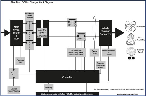
As can be seen from the diagram above, DC Chargers are more sophisticated than AC Chargers and incorporate several relays and contactors. The main switching contactors are the two HVDC contactors which break the DC load current to the vehicle. As the key safety devices, they must be able to carry the charging currents for long periods, possibly an hour or more, and be able to open under load in a fault condition.
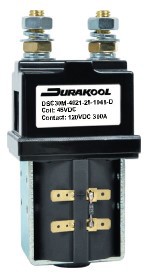
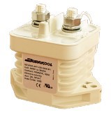
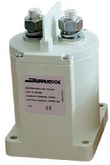
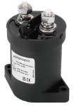
Durakool DEVR series HVDC Contactors are designed for this application. The DEVR20 and DEVR40 are used as the main break HVDC contactors as they can carry up to 600A, or more, and break a one-time load current of 2000A in an emergency.
For higher currents, the Durakool DEVR45, DEVR50 and DEVR60 can carry up to 1000A for 10 minutes, when used in a boost charger.
Considerations for choosing a HVDC Contactor for DC Fast Chargers
- Load Voltage & Current
a. Continuous carry current and voltage
b. Switching. i.e., breaking current and voltage (opening contacts) in normal operation. - Expected emergency break current.
- Coil drive voltage.
Durakool DEVR’s feature a PWM Coil Economiser to reduce coil current after initial operation. This saves power, and therefore costs, as well as unwanted heating, and has the added advantage of a wide operating range. 9 ~ 36VDC or 32 ~ 95VDC. - Terminals and Conductors.
Durakool specifies its ratings with a maximum terminal temperature rise of 70°C above ambient, in accordance with ISO (EN) 60947-1. The choice of busbars or cables will affect the temperature rise in the terminals as they conduct the heat away from the contactor. Too small a conductor will also generate its own heat and may even melt. With high voltages and currents, cable and busbar resistance are real factors to be considered. - Welded main contact detection.
Durakool DEVR’s offer an optional integral auxiliary contact mechanically linked to the main contacts which can be used to monitor the main contact position. If the main contacts have welded closed due to a problem, the auxiliary contact will not open when the coil is deenergised, thus enabling the controller to not initiate a charging cycle and to disconnect the AC supply via the main AC Contactor. - Ambient temperature ratings. i.e., the temperature inside the cabinet adjacent to the contactors.
- Physical constraints. Size and mounting.
Other Relays and Contactors for DC Fast Chargers
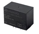
Within the Fast DC Charger, there will probably be some form of cabinet temperature control, cooling and heating, depending on where the charger is situated. Cabinet temperature sensors will activate fans and/or heaters as required. Small PCB mounting relays, or DIN Rail mounted relays with an 8A to 16A current rating at 230VAC are ideal for this. Typically, the Durakool DX87, DX85 and D2RS relays are employed, but the Durakool
DG34 or DG38 series with their 40A switching capability are worthy of consideration, especially as the range includes chassis mounting types, and PCB versions with fast-on terminals to enable wiring to be kept simple. In addition to the HVDC Contactors, AC Isolator switches and AC Over Current Circuit
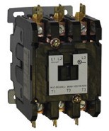
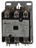
Breakers, a three-pole AC contactor is used to apply and cut the 3-Phase power to the AC/DC Converter under the control of the main processor. Durakool 30C40 series, or the larger Durakool 30C50, 30C60, 30C75 or even the Durakool 30C90 series AC Definite Purpose Contactors are suitable for use in this application.
Possible Futures: EV to grid
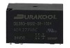
Durakool DEVR Series HVDC Contactors are available with bi-directional (non-polarised) contacts which enables them to be used in applications where the onboard batteries can supply current back to the grid via a special charger. Typically, the Durakool DEVR20-5091-S8-0936-R1 is used in such an application, but if higher currents are anticipated, then larger contactors from the Durakool DEVR series may be used. The SAE J2954 standard defines the requirements for unidirectional charging. i.e., from the wall charger to the vehicle. A standard for bidirectional charging, i.e., from the vehicle to the grid is still to be published (Spring 2022). SAE J2954 is based on, and adapted from, the J1772 Level 1, Level 2 (1-phase) and Level 3 (3-phase) charging standard.
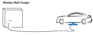 Possible Futures: Wireless Charging
Although still new and under development, wireless charging removes the need to use heavy and awkward cables to connect the charger to the vehicle. Installation requires a special wall charger and either a buried cable or an inductive charging pad for domestic use. However, the same issues of safety occur. There must be a way to disconnect the charger from the charging loops (and hence the EV), and the charger from the incoming supply, if something goes wrong.
Wireless charging requires a buried inductive loop, and trials are currently underway in various sites, with a least one car already in production, in South Korea, with the capability (2022) although it’s not yet software enabled, and others being modified for field trials in the UK, Germany and elsewhere. In the USA, at least one company is in its third generation of wireless charging pads for domestic use. Whilst trials are taking place for vehicles such as taxis and small delivery vans. Buses are also being trialed in several countries, with loops installed or proposed for bus stops along the route as well as at the main garage.
Wireless charging systems still need an AC contactor, such as the Durakool 30C40 and AC/DC relays capable of breaking the power to the inductive loop. This will not be DC, but also will not be the “normal” 50Hz or 60Hz of the typical AC supply. Relays and contactors will need to be chosen carefully to suit the system.
Hydrogen fuel cells and hydrogen combustion engine vehicles will also require relays and contactors. Hydrogen fuel cell vehicles have similar contactor requirements to those with a Lithium-Ion power source although they are likely to be self-charging (from the fuel cell) rather than requiring an external charger/power source. Hybrid designs are a possibility too.
Relays and Contactors for LVDC EV Chargers
Not all EV’s work at high voltages (above 200VDC), there are many that have batteries that operate at voltages from just 12VDC up to 96VDC. Most of these will be lead acid batteries, but now Lithium based batteries are appearing, due to their inherent lighter weight and size advantages. However, the same safety concerns exist. The voltages are high enough to pose a risk and charging currents are still high. Risk of fire or even death is possible.
Durakool has various solutions for the disconnect relays and contactors in LVDC systems. The Durakool DEVR series of HVDC contactors work very well at the lower voltages above 48VDC but are perhaps “over specified” for some applications. Durakool has introduced the Durakool DLVC400, based upon the Durakool DHVC200, precisely for these applications.
If something smaller is acceptable, then the Durakool DX71 Series of PCB relays offers a good solution, and they are latching (bistable) too, which means they don’t take any current when in the operated position, closed or open. The Durakool DX71 Series also features an integral auxiliary contact which can be used for weld detection or for simply monitoring the position of the contact. There are three versions with switching capabilities up to 80VDC and 125A (DX71D).