
- Home
- Products
- Information
- Catalogues
- Datasheets
- Product Videos
-
Technology
- Whitepaper Powering Success
- Browse Technologies
- Blowout Magnets - What They Are & Why Use Them
- Contact Resistance Versus Pressure
- Contacts Construction & Materials
- EV Battery Charging Applications - Relays & Contactors
- How to Avoid Common Relay Problems
- HVDC Contactors & Failure Modes
- HVDC Relays & Contactors Conductor Size & Heat Dissipation
- HVDC Relays & Contactors Overview
- Latching Relays
- Layman's Guide to Coil Suppression
- Relay Contact Forms - An Explanation
- Switching Polarised & Non Polarised
- Temperature effects - EMR Operation
- Applications
- About us
- News & Events
-
Latest News
- All our Latest News
- The Relay - More than just a simple black box
- ACT Expo 2025
- Enhancing energy efficiency in contactors and relays for mobile applications
- Navigating market dynamics: a power control industry perspective
- Forklift Revolution - Keeping you informed
- Durakool Distributor Conference
- Enhancing Energy Efficiency in Modern Electrical Systems
- Durakool at Detroit Battery Show 2024
- Unveiling relay solutions for EV and industrial applications
- Ensure Your Forklift Relays Don't Fail - Learn How!
- iVT Cologne - Electrification
- Absolutely worth the visit
- Istanbul EV Charge
- Engineering & Design Show 2023 - Excellent Show
- Durakool in Gothenburg
- HVDC Range Expansion 2023
- Product launch at Stuttgart Battery Show 2023
- Teamwork Appreciation - Las Vegas
- Durakool in the Fast Lane at Silverstone
- Valuable time spent with our customers
- Intro Durakool Pre-Charge & Discharge Resistors
- Great Success 2022 Battery Show
- Socking it to you!
- Dig Yourself Out of a Hole
- Keep Your Cool at the Wheel
- Need a Socket to Go with That Relay?
- Events
-
Press Releases
- All our Latest Press Releases
- Breakthrough DLVC200 and DLVC300 contactors from Durakool boost performance and reliability
- Durakool launches new high-performance DG86M relay
- Durakool unveils first-of-kind relay solution for electric vehicle and industrial applications
- Optimised, safe & reliable solutions from Durakool - iVT Expo
- Durakool Announces Expansion of High Voltage DC Portfolio
- Durakool Announces High Voltage DC Switching Contactors for Superior Isolation, Improved Reliability and Longer Service Life
- AUTOMOTIVE HIGH VOLTAGE - TWO IN ONE!
- An Easier and Safer Life with the Unique DG55M
- Move Up in the World with DG38L PCB Motor Control Relays
-
Latest News
- Contact us
- Portal
HVDC Relays & Contactors Overview
 A Quick Word about Definitions
IEC 60947 Low Voltage Directive <= 1000VAC or 1500VDC
But, in the automotive industry anything above 24VDC is called HVDC,
so
HVDC (for this presentation) = >30VDC & =<1500VDC
Special techniques needed above 1500VDC but principles are the same!
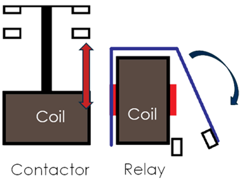
Relay = coil with solid iron core, armature is hinged and pulled to core, contacts move through an arc (even if very small).
Contactor = coil with hollow core, plunger is pulled into coil, contacts move in a straight line, usually configured as double make/break contacts (single or many poles), big contact gap.
© Willow Technologies Ltd.2019
Relay = coil with solid iron core, armature is hinged and pulled to core, contacts move through an arc (even if very small).
Contactor = coil with hollow core, plunger is pulled into coil, contacts move in a straight line, usually configured as double make/break contacts (single or many poles), big contact gap.
Electric Vehicles are not new!
1898
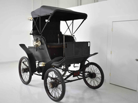
- Top speed = 40mph
- Range = 50 miles
- Won 1st automobile race in the USA (1896)
Nor is DC switching for alternative energy sources!
1887
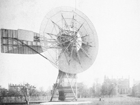
- 12kW c. 70V ~ 75VDC
- Brush was lighting New York streets 2 years before Edison!
 DC Considerations
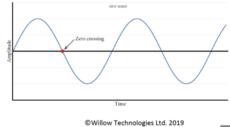
Switching low frequency (50/60Hz) AC is relatively easy.
Any switching arc is self extinguishing at the zero crossing point.
With DC there is no zero crossing to extinguish any arc formed when the contacts open.
To extinguish a DC switching arc, a big gap is needed. The gap size is dependent on the voltage.
Paschen’s Law
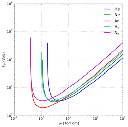 Describes the breakdown between two electrodes and gives an equation for the voltage required to start an arc.
Equation is for fixed gaps between the electrodes and for specific gas types and at defined pressures.
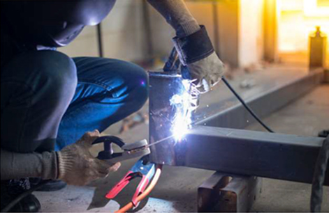
In a relay or contactor, as the contacts open, there is an infinitesimally small gap and a plasma forms between
the contacts. A stable arc is drawn out from the contacts until the gap is too big for the voltage to sustain the arc.
This is the principle of arc welding!
 When DC Currents and voltages are high enough
- Very significant contact damage can occur very quickly.
- Arc temperatures can be anywhere from 3000˚C to 20,000˚C.
- Contacts will melt and may even vaporize.
NB: Most DC switching issues occur when the contacts open but, when the contacts close there will always be some contact bounce.
Arc on contact opening Bounce arc on contact closing
Principles of DC Switching
- Make the contact gap as big as possible
- Open the contacts as fast as possible
- Stop the arc from forming
- Reduce contact bounce time
- Robust contacts and terminals to manage heat dissipation
We can make a big contact gap but how do we make the contact gap bigger if space is limited?
If we have a big contact gap, we need a big coil as it has to exert a pull over a bigger distance, bigger than would otherwise be necessary to keep the contacts closed. Bigger coil means more weight, more current (and more heat), greater cost and the increase in size.
 Arc Extinguishing – Big Contact Gaps
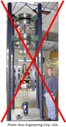
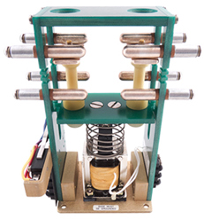
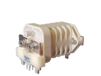
Shown on the right is a DPNC+DPNO relay designed to switch high voltage RF power.
Big contacts!
Big coil!
Big contact gaps!
Switching RF power approximates DC as far as relays & contactors are concerned.
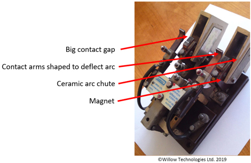
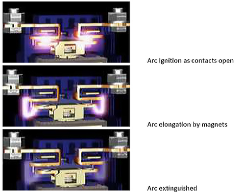
Arc Extinguishing – Big Contact Gaps and Magnets
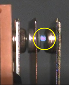
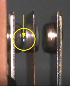
 Shown on the right is an old DPST-NO relay designed to switch 15kVDC at 15A. It is from a British railway carriage where they are still in use today.
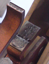
If you look closely you can see the traces!
Arc Extinguishing Small Relays
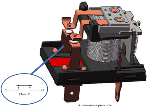 Similar techniques can be used in miniature relays.
The Durakool DE20 uses a 1 Form X contact configuration, with shaped contact arms and magnets to switch
20A @ 450VDC.
(The drawing doesn’t show the magnets.)
Arc Extinguishing with Magnets
NB: Polarity of magnets and current direction is important
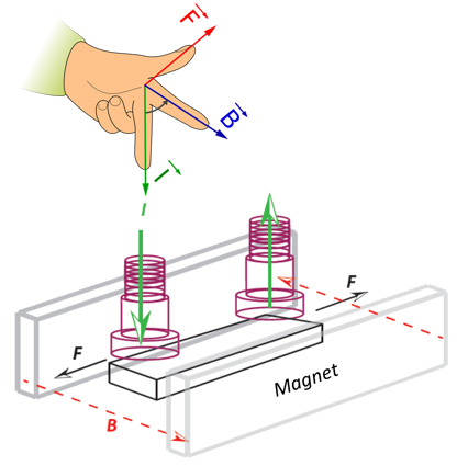
Direction of arc is controlled by Fleming's Left Hand Rule.
If terminals are incorrectly polarised, opening arcs will be deflected inwards and may not be stretched far enough to be extinguished.
Stop the Arc from Forming
The arc that forms when the contacts open is a drawn arc – like an arc welder.
If arc forms in air a stable arc will form only limited by the ability of the source to keep it supplied.
Replacing the air around the contacts with a gas with known arc limiting properties, or a vacuum, removes the Oxygen which sustains the arc.
 For this to work, contents must be inside a gas tight environment (hermetically sealed). If the seal leaks and air gets in, then there can be catastrophic results!
Various gasses have been tried with varying degrees of success:
Sulphur hexafluoride (SF6), Hydrogen (H) and Nitrogen (N) plus other more complex mixes.
Vacuum is the best solution but very difficult to achieve in production, even with steel cans and glass to metal seals. There will always be some gaseous mix which will ionise and allow an arc to form even if it is weak and easily extinguished.
Of course, it is possible to stay with air but this usually either results in a larger contactor than would be achievable with a gas fill or with reduced switching capacity.
Terminal Considerations
Even if the arc can be extinguished, it can still melt the contact surface. This will eventually lead to a contact weld.
 It is important to keep the contacts as cool as possible, both during the switching process and when the contacts are closed and conducting.
Terminals can be used to dissipate the heat into the surrounding cables and busbars.
Therefore it is important to keep the busbars (or cables) at least as large as the manufacturers recommendations and bigger if possible.
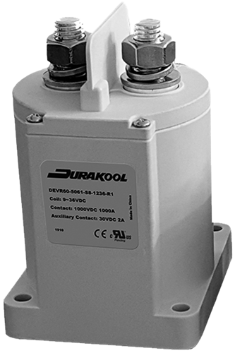
For example, Durakool DEVR60 is rated for 600A with 200mm2 busbars, but increase to 300mm2 and it can carry 1000A for 10 minutes and still remain well within acceptable terminal temperatures.
IEC (EN) 60947.1 (Table 2) defines the acceptable limits for the temperature rise, above ambient, for relay and contactor terminals.
Typically, contactor terminals will be silver plated, or nickel plated, copper or brass.
So, according to Table 2, the maximum temperature rise is 70°K.
At least one HVDC Contactor manufacturer quotes their data with a terminal temperature rise, above ambient, of 85°C, i.e. 15°K above the limit specified in IEC (EN) 60947.1
| Table 2 - Temperature rise limits of terminals (see 7.2 and 8.3, 3.3.4) | |
| Terminal material | Temperature limits K 1)3) |
| Bare copper | 60 |
| Bare brass | 60 |
| Tin plated copper or brass | 65 |
| Silver plated or nickel plated copper or brass | 70 |
| Other metals | 2) |
|
1) The use in service of connected conductors significantly smaller than those listed in Tables 9 and 10 could result in higher terminals and internal part temperatures and such conductors should not be used without the manufacturer's consent since higher temperatures could lead to equipment failure. 2) Temperature rise limits to be based on service experience or life tests but not to exceed 65K. 3) Different values may be prescribed by product standards for different test conditions and for devices of small dimensions, but not exceeding by more than 10K the values of this table. |
|
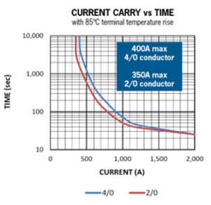
4/0 ≈ 100mm2
2/0 ≈ 60mm2
The operation temperature range for this contactor is -55°C to +85°C which means the terminals could be at 170°C when fully loaded.
 Automotive Relay Design for DC Switching
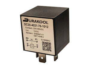
Automotive Relays are relays optimized to switch DC voltages, usually between 6VDC & 24VDC with currents from 5A to 100A.
Industry standard ISO 7588 defines the outline and package foot print.
Increased demand for automotive relays to switch 48VDC, or higher, in an ISO 7588 style package due to introduction of “48V mild hybrid” systems and the use of lithium ion batteries in industrial vehicles.
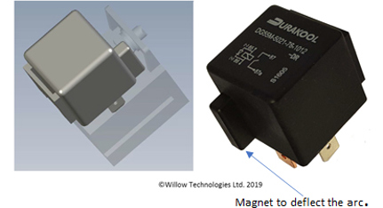
![]()
 <145VDC: 1 Form A contact (single break) Magnet deflects arc to side. >120VDC, 1 Form X (double break) Magnet deflects arcs to sides.
Using a magnet with a concentrator results in a very small relay capable of switching 10A @450VDC.
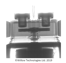
HVDC Contactor Design
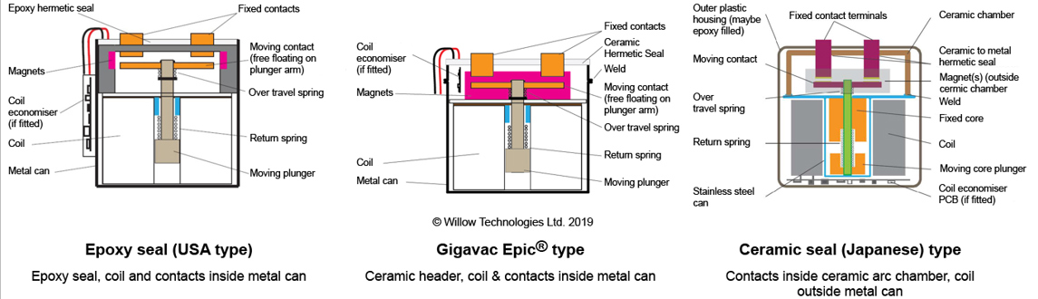
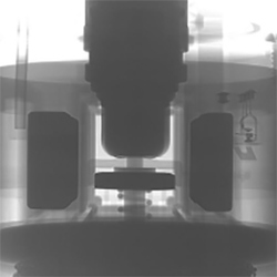 Epoxy Sealed Type
One or two magnets (2 here).
Double break Contact Gap.
Gas filled contact chamber.
Easy to manufacture in small batches.
Epoxy seal: Production is limited by curing oven capacity and time.
‘Japanese’ Style
More costly to manufacture with heavy initial investment in assembly equipment
But good for automation and quick assembly. No curing time for epoxy.
Fully automatic assembly possible.

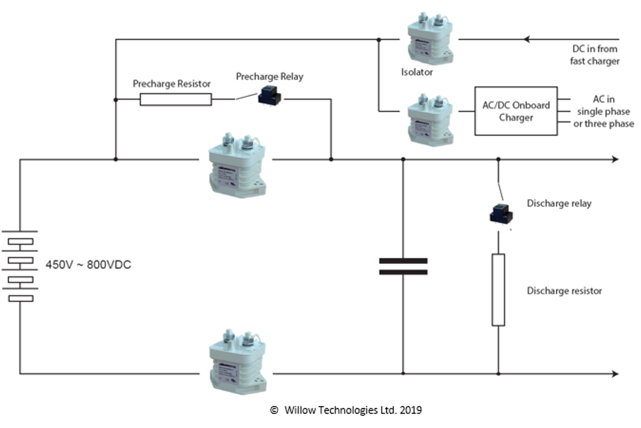
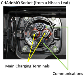
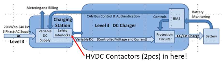
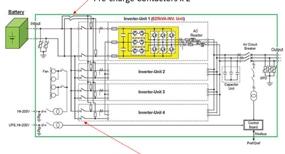
Typical Application in an EV
Contactors are used to provide safety isolation of the battery.
They do not normally switch under load, but they do have to withstand high peak currents when vehicle accelerates for example.
Sequence of operation
- Discharge contactor opens (often a NC type).
- Pre-charge relay closes and filter capacitors start charging. Current is limited by the Pre-charge resistor.
- Main contactors close when capacitors are at about 80% charge.
- Pre-charge relay opens until next cycle.
- EV comes to a stop and switched off. First Main contactor opens and Discharge relay closes to drain excess voltage from capacitors - safety – and then Second Main contactor opens to isolate battery.
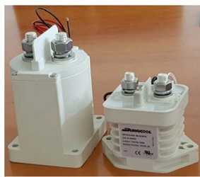
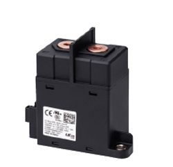
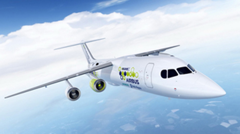
Not All EVs are Cars!
![]()
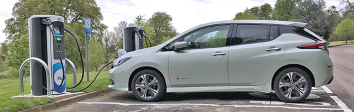
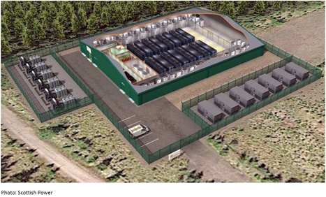
DC Fast Charging
Solar & Wind Power

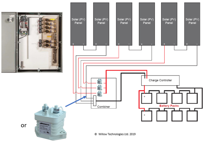
Not All Solar Panel Installations are in Huge Fields
New designs of solar cells enable portable applications for disaster recovery, emergency power or military applications.
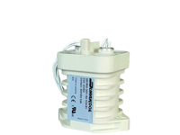
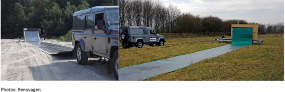
HVDC Relays or contactors used for safety disconnect.
50A/750VDC
Summary
One person’s HVDC is another person’s LVDC! HVDC for many = >24VDC and <1500VDC.
Switching DC above 24VDC is not a new problem, but increasing use of new batteries, together with new technology, is generating fresh challenges for relay and contactor makers.
Switching HVDC is all about coping with switching arcs and maintaining insulation and isolation.
Innovations in batteries mean high power batteries which for safety must be isolated from the rest of the system when not in use or in the event of a fault.
Relays & Contactors used in EV applications have to be as small as possible but still carry high currents whilst maintaining isolation and insulation distances for voltages in excess of 1000VDC.
Contactors in EV’s must be capable of breaking a fault (short circuit) current at least once but do not normally switch under full load.
They must carry the full load current for long periods and cope with short term peak currents for several minutes.
Contactors for PV and Battery Storage Systems must be capable of breaking fault currents at least once but may also have to switch full load current several times during the expected life.
Contactors used in battery storage DC to AC systems share much in common with EV’s except higher voltages and currents.
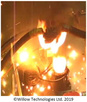
Get it wrong and the results can be dramatic!