
- Home
- Products
-
Information
- Catalogues
- Compliance
- Datasheets
-
Technology
- Browse Technologies
-
Application Notes
- Blowout Magnets - What They Are & Why Use Them
- Contact Resistance Versus Pressure
- Contacts Construction & Materials
- EV Battery Charging Applications - Relays & Contactors
- HVDC Relays & Contactors Conductor Size & Heat Dissipation
- HVDC Relays & Contactors Overview
- Latching Relays
- Layman's Guide to Coil Suppression
- Relay Contact Forms - An Explanation
- Switching Polarised & Non Polarised
- Installation
- User Manuals
- Whitepapers
- Videos
- Applications
- About us
-
News & Events
-
Latest News
- All our Latest News
- Managing Relay Vibration in Industrial Vehicle Control Systems
- The Physics Wall
- How Advanced Relay Contact Design Transforms Forklift Reliability
- OEM Finland Oy at Helsinki's Teknologia '25
- TMS Elektronik at EV Charge - Istanbul
- Jinzon at Energy Taiwan 2025
- New HVDC Contactor 800A @ 1500VDC
- The Great Relay Debate
- iVT Expo Germany reflections
- Custom or Standard?
- The Relay - More than just a simple black box
- ACT Expo 2025
- Enhancing energy efficiency in contactors and relays for mobile applications
- Navigating market dynamics: a power control industry perspective
- Forklift Revolution - Keeping you informed
- Durakool Distributor Conference
- Enhancing Energy Efficiency in Modern Electrical Systems
- Durakool at Detroit Battery Show 2024
- Unveiling relay solutions for EV and industrial applications
- Ensure Your Forklift Relays Don't Fail - Learn How!
- iVT Cologne - Electrification
- Absolutely worth the visit
- Istanbul EV Charge
- Engineering & Design Show 2023 - Excellent Show
- Durakool in Gothenburg
- HVDC Range Expansion 2023
- Product launch at Stuttgart Battery Show 2023
- Teamwork Appreciation - Las Vegas
- Durakool in the Fast Lane at Silverstone
- Valuable time spent with our customers
- Intro Durakool Pre-Charge & Discharge Resistors
- Great Success 2022 Battery Show
- Socking it to you!
- Dig Yourself Out of a Hole
- Keep Your Cool at the Wheel
- Need a Socket to Go with That Relay?
- Events
-
Press Releases
- All our Latest Press Releases
- Breakthrough DLVC200 and DLVC300 contactors from Durakool boost performance and reliability
- Durakool launches new high-performance DG86M relay
- Durakool unveils first-of-kind relay solution for electric vehicle and industrial applications
- Optimised, safe & reliable solutions from Durakool - iVT Expo
- Durakool Announces Expansion of High Voltage DC Portfolio
- Durakool Announces High Voltage DC Switching Contactors for Superior Isolation, Improved Reliability and Longer Service Life
- AUTOMOTIVE HIGH VOLTAGE - TWO IN ONE!
- An Easier and Safer Life with the Unique DG55M
- Move Up in the World with DG38L PCB Motor Control Relays
-
Latest News
- Contact us
- Portal
HVDC Contactors and Failure Modes
Typically an electric vehicle (EV) will have two main contactors which are positioned in the feed from the battery to the electronic motor drive. There may be others used as part of the pre-charge, discharge or charging circuits. The principal function of the main contactors is to isolate the battery from the rest of the system when the vehicle is not being used and when an emergency occurs which requires immediate disconnection of the battery for safety reasons.
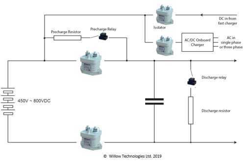
The electric motor drive will have a substantial inrush current when the contactors close (from the input capacitors). To avoid failure of the main contactors caused by the inrush, some form of pre-charge circuit is employed to reduce the inrush current. Contact failure caused by the inrush current is mainly due to arcing when the contacts bounce as they close. The very high inrush current during closing generates an arc which melts the contact surface and they “stick” or weld together in the closed position as the contacts cool down when the current drops to the normal run current. The use of a pre-charge circuit helps to reduce the inrush current which, in turn, reduces the arc current to a level that the contacts can handle with ease. Correct specification of the pre-charge circuit is important to ensure the main contactor’s contacts do not wear or weld.
Fig. 1: Typical EV Battery System
When the EV normally comes to a stop and is turned off, the electric motor drive reduces the current to a very low level and the main contactors open. There is no arcing.
The safety function of the main contactors requires them to open in an emergency and interrupt the current flowing from the battery. In an accident, or a catastrophic failure, this could mean the contactors must break the full battery short circuit current as a safety precaution even though fuses will also be incorporated into the battery system, thus isolating the battery from the rest of the vehicle. Of course, this is a one time only situation where the contactors must be replaced as part of the repairs and maintenance after such an event.
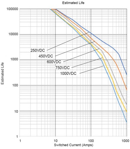
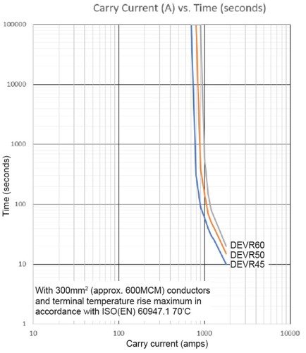
Fig. 2: Typical estimated life graphFig. 3: Typical carry current graph
It can be seen that in normal conditions, and with the correct pre-charge circuit, the contactors have a relatively easy life. Or so it would appear …
HVDC Contactor data sheets focus on the maximum current and voltage that the contactor can carry and switch. Most data sheets include graphs which show the estimated life for when the contactor is switching (making and breaking) under load and a graph which shows the current carrying capabilities relative to time for a specified conductor cross section.
ISO (EN) 60947.1 specifies a maximum terminal temperature rise of 70°C above ambient and this will dictate the conductor cross section. The higher the current, the larger the conductor cross section. There will also be a 1 time only maximum current quoted in the data, for the safety break function. But this information only tells part of the picture. To examine possible failure modes, we must look more closely and understand a bit more about the HVDC contactor’s construction and how it works.
Direct current (DC), and especially any DC voltage above 24V, is difficult for a contactor or a relay to switch, making or breaking, because the DC arc generated in air when the contacts open is only extinguished by distance between the contacts. Generalising, the higher the voltage, the bigger the gap required. (AC is different as it self-extinguishes as it goes through the zero-crossing point.)
The primary method to break a DC arc is to use a large contact gap, combined with a suitable contact material, so that the arc goes out before it causes significant damage to the contact rivets or studs. Contactors have double contact gaps which offers inherent advantages over relays, for DC switching, especially at higher voltages and currents.
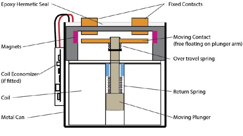
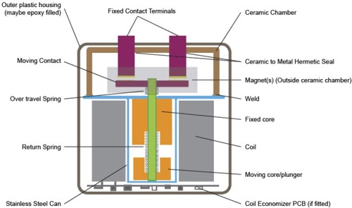
Fig. 4: Typical epoxy seal designFig. 5: Typical ceramic chamber design
The HVDC contactor designer can use several methods to improve the DC switching capacity. The contact chamber may be hermetically sealed and filled with a gas which helps to stop the arc forming and they will probably use 1 or more magnets to deflect, or “blow-out”, the DC arc and extend the arc length. The shape of the fixed contacts and the moving contact arm will also be tailored to work with the mag-nets. Positioning of the magnets is important as they may polarise the terminal connections. The current must flow in the correct direction for the arc to be deflected away from the contacts. If the current flows in the wrong direction, the arc will be deflected inwards, along the moving contact arm and may not be extinguished. Some HVDC contactors, such as the Durakool DEVR’s, use more than one magnet to ensure the contactor is not polarised and can break the load current in either direction. In general, HVDC contactors are not polarised when the contacts are closed, current may flow in either direction, but there are other issues which may need to be taken into consideration. How the magnets work is the subject for another, more detailed, article.
It must be remembered that an arc is generated when the contacts open, but when the contacts close, they bounce open. Each time the contacts bounce open an arc is generated which will lead to contact wear. If there is a big inrush current during the bouncing time period, serious arcing could occur causing the contacts to weld in the closed position. The arc melts the contact surface and a weld occurs when the contacts finally rest in the closed position.
The magnet has little effect as the time is very short and the gap is very small. Therefore, it is common to see graphs which show a line indicating “Breaking only” above a certain current and voltage (Fig. 6).
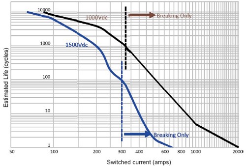
Fig. 6: Typical estimated life graph with “Breaking only” indicated
When the coil is de-energised and the contacts open, the return spring (see Figs 4 & 5) opens the contacts quickly and the contact gap, combined with the “blow-out” magnets, is big enough to fully extinguish the arc before any significant contact damage can occur. However, it is important to note that each time the contacts open and close, there will be contact degradation and hence a finite life. The contactor manufacturer will choose appropriate materials and dimensions to achieve the expected current, voltage and life characteristics. This can lead to externally physically identical contactors with different ratings as the internal components have been adjusted for the target rating. E.g., the Durakool DEVR20, DEVR25, DEVR30, DEVR35 and DEVR40 all share the same external appearance but cover a range of different current ratings.
The correct specification of the pre-charge circuit is important to avoid contact damage when the main contactors turn on. Looking at an actual example of a Durakool DEVR30 which failed in an EV we can see how the contactor has been damaged by incorrect specification of the pre-charge circuit. In this application, the contactor was switching approximately a voltage differential of 33V and a battery voltage of 650VDC and a pre-charge time of 1.6 seconds, in a battery charging system.
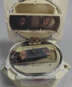
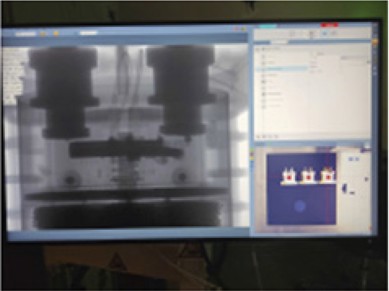
Fig. 7: DEVR30 showing contact damageFig. 8: X-ray of DEVR30 showing contact damage
So why do we see the damage above? The moving contact arm is severely eroded and the fixed contacts ablated with molten metal particles showered in the contact chamber! We have to look closer at what is occuring to understand what has happened and what steps need to be taken to resolve the issue.
The battery is a capacitive load and the load current “I” when the contactor closes is given by the formula :
I = [((V1-V0)/R)]e-(t/CR)
Where
V0 = the initial voltage (V)
V1 = the battery system voltage
R = loop resistance (i.e. battery internal resistance + connection resistance) C = capacitance (in Farads F)
T = charging time (seconds)
At the moment of pull-in (contact closure) it can be approximated that the battery charging time t= 0 and the formula can be simplified:
I = (V1-V0)/R
It can be seen that the contact load current “I” is directly proportional to the voltage difference when the contactor contacts close
.
Going further, we see, in this application, the battery voltage was 650V and the pre-charge was at 617VDC and therefore the voltage differential is 33V, the internal resistance of the battery is approximately 200mΩ and the contact resistance of the contact path is about 2mΩ. The steady state current when the battery is charged is calculated as 33/0.202 = 163.4A which is well within the DEVR30 parameters. But, the battery is a capacitive load and its load surge current is 10 to 20 times (or even higher) the steady state current which means the current at the point of contact closure could be anywhere from 1500A to more than 3000A! This exceeds the capacity of the DEVR30 and significantly reduces the contact life because of the arcing during the bounce time.
The Inrush waveform looks like this…
Fig. 9: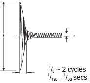
Contact bounce only exacerbates the problem as an arc occurs each time the contacts bounce open.
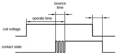
Fig. 10: Contact timing
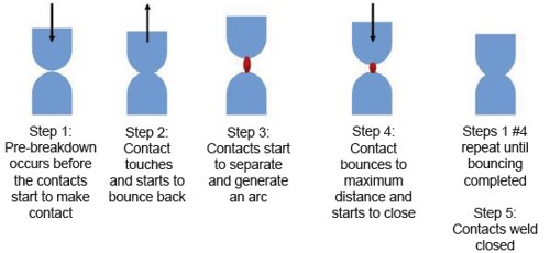
Fig. 11:
In this application, the solution was to reduce the voltage differential to 20VDC.
So far, we have only looked at what happens when the contactor is energised and de-energised. We must also look at the situation when the contacts are closed, and current is flowing through the contacts. Usually, this current will rise and fall as the EV accelerates and brakes. If the HVDC contactor is used as part of the charging circuit, there may also be a high inrush through that contactor as the battery charging commences.
A perhaps not obvious issue occurs when high currents and voltages are flowing through the contact path. When a current flows through a conductor it generates a magnetic field - that’s the principle of the contactor coil. But the magnetic fields can be a problem as well as being useful.
The current, which can be several 100’s, or even 1000’s of amps, flows through the contact path from one terminal to another. This generates a magnetic field in the contact path from static contact to moving contact and back to the other static contact in a loop which has the effect of attempting to force the contacts apart.
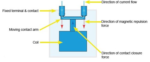
Fig. 12:
Durakool contactors use an over-travel spring (see Figs 4 & 5) to help resist the tendency for the contacts to move apart and reduce contact pressure, or even momentarily open, under extreme currents. The over-travel spring is chosen to suit the current rating of the contactor and the amount of over-travel required, along with the coil power needed to hold the contacts closed against both the over-travel spring and the return spring pressures. One extra advantage of the over-travel spring is that it can assist with keeping the contact pressures within operating parameters as the contacts ablate with time.
Should the current momentarily force the contacts open, arcing may occur which will lead to contact degradation and higher temperatures at the terminals. If the current is excessive, catastrophic damage will occur.
In the event of high current arcs well in excess of the design parameters, it’s even possible for the contactor to explode!
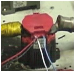
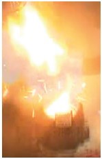
Fig. 13:
When choosing a HVDC contactor care must also be taken to consider potentially unexpected loads during use. Performance EV’s may be expected to be driven in a different manner to “normal” vehicles with repeated peak current surges and more frequent charging cycles.
Frequent peak surges without time for the contactor to cool between each surge could cause the contacts to fail, especially if the surge current is enough to overcome the over-travel spring keeping the contacts in the closed position. The likely failure in these conditions is the contacts welding closed. On the other hand, often repeated charging cycles will lead to an accelerated end of life or possible premature failure due to contact ablation. Worst case is a catastrophic failure.
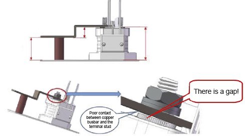
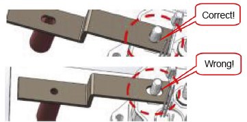
Fig. 14:Fig. 15:
Finally, another cause of failures is poor connection to the contactor power terminals. This is not unique to HVDC contactors but also a problem for all contactors and relays that carry significant currents. Particular care must be taken to ensure that the busbar or ring ter-minal is flat against the contactor power terminal. This can be a problem with thicker busbars or busbars that do not have flexibility. Soft copper is better. Likewise, a loose mounting hole for the terminal will be a source of issues.
In both instances, the increased resistance will cause overheating of the power contacts which will also lead to pre-mature failures.
Failures in HVDC contactors can occur in both a sudden catastrophic manner, and over time as the contacts age and wear. Assuming the contactor is correctly matched with the application parameters and not likely to fail catastrophically, we need to identify a method of determining the imminent end of life for the contactor apart from counting the number of operations.
When the contacts are damaged by arcing, their contact resistance increases. We can say that if the contact resistance increases by 30% or more, then it is time to replace the contactor. One direct effect of the increase in resistance is an increased temperature on the contact terminals. So, an indirect way of measuring the contact resistance could be to monitor the temperature rise on the terminals at a known ambient temperature and fixed current. Another method could be to monitor the insulation resistance, although this would be harder to achieve in practice. Typically Durakool contactors have an initial insulation resistance of 100MΩ. As the contactor ages, the insulation resistance decreases due to the materials from the arcing building up inside the contact chamber. The photo (Fig. 7) above shows the build up of debris from arcing inside the contact chamber very clearly. End of life is declared when the insulation resistance is reduced to 50MΩ.