
- Home
- Products
- Information
- Catalogues
- Datasheets
- Product Videos
-
Technology
- Whitepaper Powering Success
- Browse Technologies
- Blowout Magnets - What They Are & Why Use Them
- Contact Resistance Versus Pressure
- Contacts Construction & Materials
- EV Battery Charging Applications - Relays & Contactors
- How to Avoid Common Relay Problems
- HVDC Contactors & Failure Modes
- HVDC Relays & Contactors Conductor Size & Heat Dissipation
- HVDC Relays & Contactors Overview
- Latching Relays
- Layman's Guide to Coil Suppression
- Relay Contact Forms - An Explanation
- Switching Polarised & Non Polarised
- Temperature effects - EMR Operation
- Applications
- About us
- News & Events
-
Latest News
- All our Latest News
- iVT Expo Germany reflections
- Custom or Standard?
- The Relay - More than just a simple black box
- ACT Expo 2025
- Enhancing energy efficiency in contactors and relays for mobile applications
- Navigating market dynamics: a power control industry perspective
- Forklift Revolution - Keeping you informed
- Durakool Distributor Conference
- Enhancing Energy Efficiency in Modern Electrical Systems
- Durakool at Detroit Battery Show 2024
- Unveiling relay solutions for EV and industrial applications
- Ensure Your Forklift Relays Don't Fail - Learn How!
- iVT Cologne - Electrification
- Absolutely worth the visit
- Istanbul EV Charge
- Engineering & Design Show 2023 - Excellent Show
- Durakool in Gothenburg
- HVDC Range Expansion 2023
- Product launch at Stuttgart Battery Show 2023
- Teamwork Appreciation - Las Vegas
- Durakool in the Fast Lane at Silverstone
- Valuable time spent with our customers
- Intro Durakool Pre-Charge & Discharge Resistors
- Great Success 2022 Battery Show
- Socking it to you!
- Dig Yourself Out of a Hole
- Keep Your Cool at the Wheel
- Need a Socket to Go with That Relay?
- Events
-
Press Releases
- All our Latest Press Releases
- Breakthrough DLVC200 and DLVC300 contactors from Durakool boost performance and reliability
- Durakool launches new high-performance DG86M relay
- Durakool unveils first-of-kind relay solution for electric vehicle and industrial applications
- Optimised, safe & reliable solutions from Durakool - iVT Expo
- Durakool Announces Expansion of High Voltage DC Portfolio
- Durakool Announces High Voltage DC Switching Contactors for Superior Isolation, Improved Reliability and Longer Service Life
- AUTOMOTIVE HIGH VOLTAGE - TWO IN ONE!
- An Easier and Safer Life with the Unique DG55M
- Move Up in the World with DG38L PCB Motor Control Relays
-
Latest News
- Contact us
- Portal
Contact Resistance Versus Contact Pressure
Introduction
There has long been accepted that there is a relationship between contact resistance and contact pressure (e.g. Ragnar Holm, Electric Contacts handbook 1958 and subsequent editions). This paper seeks to simplify the wealth of information available (mostly highly detailed equations) from learned Papers and other publications, and to discuss how this might have relevance to the everyday application of electro mechanical relays. The basis is that as the contact pressure increases the contact resistance decreases. Obviously, there are limits in practice and we’ll discuss those further later on. This does not apply to mercury wetted contacts where the conditions are very different.
It’s also important to note that in the context of this discussion and as used in the Papers, “load” means the mechanical pressure on the contacts and not, as we frequently somewhat incorrectly use the word, the electrical load in terms of Amps and Volts. “Relays” in this context refers to electro-mechanical relays and contactors that have solid metal contacts that close when driven by a coil.
How a relay works
In simplistic terms, a current flowing through a coil generates a magnetic field. That magnetic field is used to make an armature move. A contact (the moving contact) is fixed to the armature and makes a physical connection with a fixed contact to complete the circuit. Various factors have to be taken into account to ensure that the magnetic circuit is as efficient as possible, and there is a direct correlation between the coil power needed to generate the magnetic field and the distance over which the magnetic field has to operate in order to get the armature, with its contact, to move. Basically, the bigger the gap, the more coil power is needed. Increased coil power has negative effects, especially with heat generation in the coil (another subject), but also means that the coil itself (and by extension, the relay) has to be physically larger. As a consequence of the resistance of copper changing with temperature, the amount of coil power required is also directly proportional to the ambient temperature around the coil. Therefore, an efficient design of the magnetic circuit is important to keep size and heat to the minimum practical.
Next, we have to look at what happens when the contacts close. If the armature (and contact blade with its contact) is rigid, the contacts will close when the coil is energized but bounce apart several times before coming to rest in the closed position. The coil applies pressure, via the magnetic circuit, to the moving contact to hold the contacts closed. More coil power is needed to overcome the inertia and to pull the armature across the gap than is required to hold the contacts closed. This can be seen in larger “solenoid” style relays which have an operate coil and a separate hold coil which is engaged, once the contacts have closed. As the gap between the armature and the coil decreases less energy is required. (It should be noted that most styles of latching relay, such as our DG76 or DG79, do not rely on the coil itself to hold the contacts in the closed position).
However, the contact bounce can lead to other problems (e.g. arc damage to the contacts) so the moving contact in a relay is normally fixed to a flat blade with some “springiness”. Contactors are somewhat different in design and the “springiness” is usually built in with the aid of an actual spring assembly. Either way, this helps to reduce contact bounce when used in conjunction with a design that allows over travel of the armature beyond the point the contacts touch. Now, the coil power has to hold the contacts closed against the pressure from the over travel in the springy blade, and for the majority of relays, latching types excepted, together with the pressure exerted by the return spring required to open the contacts when the coil is de-energized. There is a fine design “balancing act” between the coil power required and the amount of over travel and the return spring strength. With clever design, the over travel can also be used to wipe the moving contact against the fixed contact and this helps to clean the surface of the contact rivets of any contamination that might be there.
So, for the purposes of this discussion we can conclude that the normally open contact pressure is derived from a combination of coil power and spring pressure for when the coil is operated; and for changeover relays, the normally closed contact pressure is derived from a combination of the return spring strength and any over travel that might be built into the system via the moving contact blade.
You will note that typical automotive relays, and miniature power relays switching more than 30A, have normally closed contacts which are rated less than the normally open contacts. (e.g. DG85 series or DG34 series). This is because the contact pressure on the normally closed contact is less than the contact pressure on the normally open contacts when held closed by the coil, to keep the coil power requirement as low as possible. We can conclude that there is a correlation between contact pressure and contact current ratings.
What is contact resistance and how does it affect our higher current relays?
Contact resistance is loosely defined as the resistance between the closed contacts, but it is very small and cannot be measured using a simple multi-meter. It is made up of a combination of resistances…
Rcontact = RC + RF + RS Where
Where
Rcontact = contact resistance
Rc = constriction resistance
RF = Film resistance
RS = spread resistance (inherent
resistance of the contact material itself)
(source: Elesta GmbH)
• The cleaner the contact surface, the lower the specific resistance.
• The more uniform the surface, the lower foreign substances on the layer.
• The higher the contact force, the lower the contact resistance!
So what is happening?
The film resistance is the resistance caused by materials deposited on to the contact during manufacture and later during the life of the relay. This will leave a very thin layer of an insulating “goo” across the face of the contact rivet. The smoother the contact surface, the less the insulating layer will be but, of course, it is impossible to make a perfectly smooth surface.
Any current between the contacts will have to “punch” through this layer. This is usually referred to as “fritting” and is a whole other subject! There are two fundamental types of fritting “A-fritting” where the arc penetrates the organic cover forming a “tunnel” but the organic layer covers the “tunnel” over when the contacts open, and “B-fritting” where the “tunnel” is stable after the contacts open.
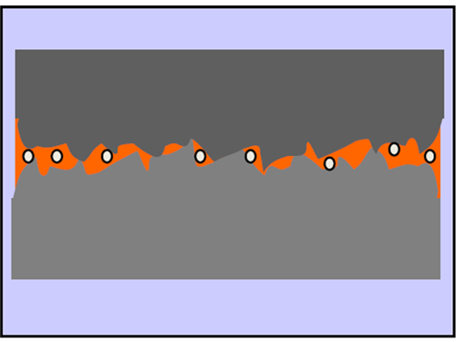
It was once supposed that the contact area was the complete surface on the contacts, but it would be more accurate to call it the apparent surface area. The actual contact area may be very small indeed. This is because the two surfaces are not perfectly smooth and there will be deformities in the contact surface. Even allowing for the softness of the contact material to deform as the contacts come together, there will still be “spots” of contact rather than one single large area. The constriction resistance is a consequence of the current flow being constricted through the small conducting spots which extend into both contacts. In fact, the total constriction resistance is made up from the sum of the constriction resistances in each contact. The number of spots where the contacts touch will vary from one contact closure to another and will be affected by plastic and elastic deformation of the contact surfaces. It can be shown that after a number of operations, depending on the contact material, contact pressure (load) and temperature, the constriction resistance will stabilize if contact pressure and temperature remain constant. If the contact pressure (load) is relatively small, elastic deformation occurs in the contact rivets instead of plastic deformation. The effect of this is to increase the constriction resistance as the load (contact pressure) is reduced, due to the “spots” shrinking as they elastically deform back their original state. For those interested, there are some very extensive proofs in the form of calculations in the aforementioned handbook.
Contact resistance (i.e. the sum of the resistances mentioned above) is important on several fronts for our power relays. Firstly, it will contribute to heat rise inside the relay, and secondly it will waste energy, mostly as heat, which might be important in a battery application (for example). Looking at the heat rise, it will be agreed that we need to keep the heat at the contact point low enough to stop the contact material from melting. Should this occur then the contacts will be damaged and may even be welded together. This can happen as the molten material has a very low contact resistance, in affect there is infinite contact at the melt point, which means that the heat is no longer generated by the contact resistance. This leads to the cooling of the contact junction, and if it falls below the melt temperature of the contact material, the contacts will be permanently connected together (welded). In an actual application it is possible that the return spring pressure is enough to break the weld once it has formed, but the contact surface will have been damaged and there is a strong possibility that the next time the relay opens an arc will form at the same point as the original melt point and the contact will be further damaged. Eventually the melt becomes so extensive that the contacts permanently weld together or the contact is completely destroyed. A commonly encountered pre-cursor to this situation is when the contacts open and pull a thin whisker of melt material which stays in place between the two contact surfaces when the relay comes to rest with the moving contact not fully open. A quick tap, or a shock in the application, breaks the whisker of metal and the contact opens fully. This is known as a micro-weld and can be difficult to diagnose as the relay will appear to function normally until the next time the whisker forms again. Eventually the relay welds permanently.
Not much can be done about constriction resistance, nor about film resistance apart from mechanical design of the contact system to ensure that the contacts wipe themselves clean as much as possible when they close and ensuring the cleanliness of the production process. In any case, contacts will gain a film (even gold plated) simply through storage before assembly and subsequently in storage before usage as a relay. Designs such as crown contacts, cross bar contacts and bifurcated contacts (twin) increase the contact pressure at the constriction points which helps to break through the surface films and to ensure reliable switching at low currents. At high currents they serve little use and may even cause problems due to the limited area for current carrying.
However, the resistance of the contact rivet material itself can be altered by the choice of the contact material alloys and the rivet construction – and that is another subject altogether!
In conclusion, we can see that control of the contact resistance is important for the best performance of the relay and that the greater the contact pressure the better from a contact resistance point of view. We can also conclude that there is compromise in the design of electro-mechanical relays between the contact pressure and the coil power required to make the optimum contact closure.