
- Home
- Products
- Information
- Catalogues
- Datasheets
- Product Videos
-
Technology
- Whitepaper Powering Success
- Browse Technologies
- Blowout Magnets - What They Are & Why Use Them
- Contact Resistance Versus Pressure
- Contacts Construction & Materials
- EV Battery Charging Applications - Relays & Contactors
- How to Avoid Common Relay Problems
- HVDC Contactors & Failure Modes
- HVDC Relays & Contactors Conductor Size & Heat Dissipation
- HVDC Relays & Contactors Overview
- Latching Relays
- Layman's Guide to Coil Suppression
- Relay Contact Forms - An Explanation
- Switching Polarised & Non Polarised
- Temperature effects - EMR Operation
- Applications
- About us
- News & Events
-
Latest News
- All our Latest News
- The Relay - More than just a simple black box
- ACT Expo 2025
- Enhancing energy efficiency in contactors and relays for mobile applications
- Navigating market dynamics: a power control industry perspective
- Forklift Revolution - Keeping you informed
- Durakool Distributor Conference
- Enhancing Energy Efficiency in Modern Electrical Systems
- Durakool at Detroit Battery Show 2024
- Unveiling relay solutions for EV and industrial applications
- Ensure Your Forklift Relays Don't Fail - Learn How!
- iVT Cologne - Electrification
- Absolutely worth the visit
- Istanbul EV Charge
- Engineering & Design Show 2023 - Excellent Show
- Durakool in Gothenburg
- HVDC Range Expansion 2023
- Product launch at Stuttgart Battery Show 2023
- Teamwork Appreciation - Las Vegas
- Durakool in the Fast Lane at Silverstone
- Valuable time spent with our customers
- Intro Durakool Pre-Charge & Discharge Resistors
- Great Success 2022 Battery Show
- Socking it to you!
- Dig Yourself Out of a Hole
- Keep Your Cool at the Wheel
- Need a Socket to Go with That Relay?
- Events
-
Press Releases
- All our Latest Press Releases
- Breakthrough DLVC200 and DLVC300 contactors from Durakool boost performance and reliability
- Durakool launches new high-performance DG86M relay
- Durakool unveils first-of-kind relay solution for electric vehicle and industrial applications
- Optimised, safe & reliable solutions from Durakool - iVT Expo
- Durakool Announces Expansion of High Voltage DC Portfolio
- Durakool Announces High Voltage DC Switching Contactors for Superior Isolation, Improved Reliability and Longer Service Life
- AUTOMOTIVE HIGH VOLTAGE - TWO IN ONE!
- An Easier and Safer Life with the Unique DG55M
- Move Up in the World with DG38L PCB Motor Control Relays
-
Latest News
- Contact us
- Portal
HVDC Relays & Contactors Conductor Size & Heat Dissipation
Principles of DC Switching: Heat, the BIG enemy!
- Make the contact gap as big as possible
- Open the contacts as fast as possible
- Stop the arc from forming
- Reduce contact bounce time
- Robust contacts and terminals to manage heat dissipation
In order to perform items 1 and 2, the easy way is to increase coil power. This will create enough pull in force to close big contact gaps, and can also open and close faster. But this means a bigger power dissipation, in other words, more HEAT.
The other big heat source in a relay or contactor, are the contacts. All current passing through the contacts is concentrated on a small surface, creating hot points. In order to minimise this heat generation we can increase contact dimensions and increase contact force to reduce contact resistance. In addition, all current carrying paths must be kept as short as possible.
Terminal Temperature Considerations:
It is important to keep the contacts as cool as possible, both during the switching process and,when the contacts are closed and conducting, to extend contact life and avoid damage or welding.
 Even increasing contact dimensions and contact force, in most cases, is not enough to keep contacts at temperatures inside limits established by IEC (EN) 60947.1.
Maximum terminal temperature rise is 70°K over ambient temperature. Built in terminals can be used to dissipate the heat into the surrounding cables and busbars.
Therefore it is important to keep the busbars (or cables) cross sectional area at least as large as the manufacturer’s recommendations and bigger if possible.
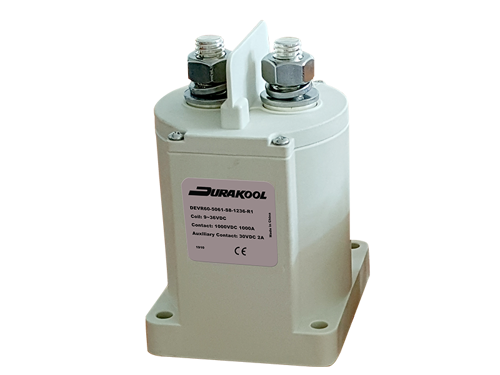
For example, Durakool DEVR60 is rated for 600A with 200mm2 busbars, but increase to 300mm2 and it can carry 1000A for 10 minutes and still remain well within acceptable terminal temperatures.
| Table 2 - Temperature rise limits of terminals (see 7.2 and 8.3, 3.3.4) | |
| Terminal material | Temperature limits K 1)3) |
| Bare copper | 60 |
| Bare brass | 60 |
| Tin plated copper or brass | 65 |
| Silver plated or nickel plated copper or brass | 70 |
| Other metals | 2) |
|
1) The use in service of connected conductors significantly smaller than those listed in Tables 9 and 10 could result in higher terminals and internal part temperatures and such conductors should not be used without the manufacturer's consent since higher temperatures could lead to equipment failure. 2) Temperature rise limits to be based on service experience or life tests but not to exceed 65K. 3) Different values may be prescribed by product standards for different test conditions and for devices of small dimensions, but not exceeding by more than 10K the values of this table. |
|
Typically, contactor terminals will be silver plated, or nickel plated, copper or brass.
So, according to Table 2, the maximum permissible temperature rise is 70°K [above ambient].
At least one HVDC contactor manufacturer quotes their data with a terminal temperature rise, above ambient, of 85°C, i.e. 15°K above the limit specified in IEC (EN) 60947.1
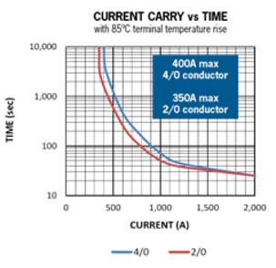
4/0 ≈ 100mm2
2/0 ≈ 60mm2
The operating temperature range for this contactor is -55°C to +85°C which means the terminals could be at 170°C when fully loaded!
For all our DEVR HVDC contactors range, we specify the minimum cable size and the recommended one.
All our continuous current charts specify the cable size used for Testing.
At least two HVDC contactor manufacturers quote their data with “Extrapolated” information.
Ask our experts about your specific application.
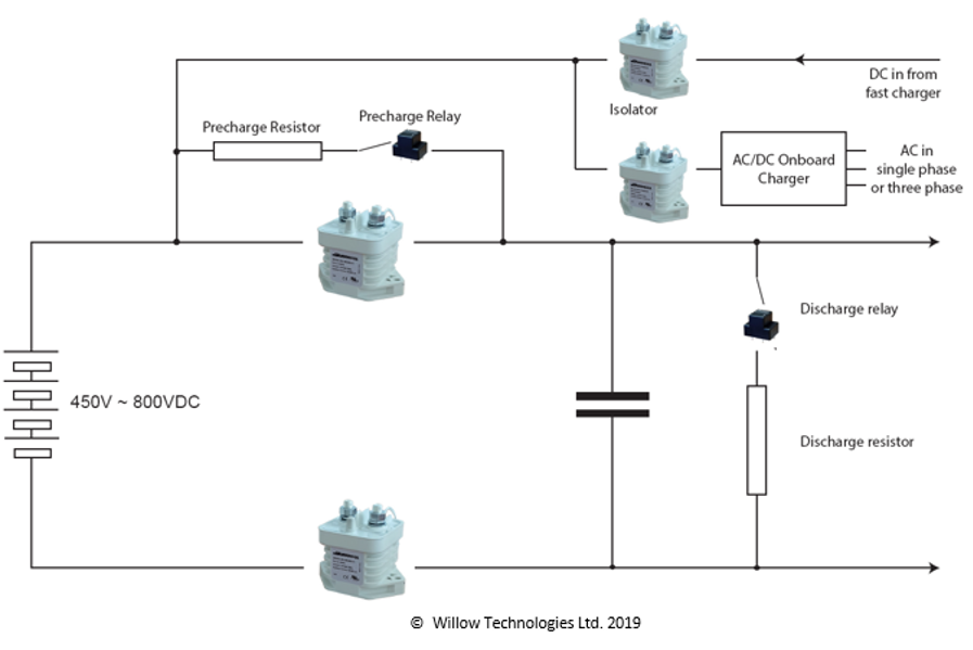
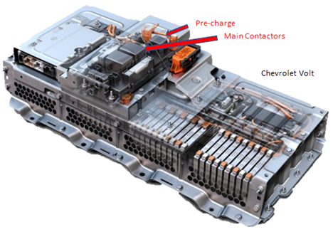
Typical Application in an EV:
Contactors are used to provide safety isolation of the battery.
They do not normally switch under load, but they do have to withstand high peak currents when vehicle accelerates for example.
Sequence of operation
- Discharge contactor opens (often a NC type)
- Pre-charge relay and 0V (-ve) main contactor close and filter capacitors start charging. Current is limited by the Pre-charge resistor.
- Second (+ve) main contactor closes when capacitors are at about 80% charge.
- Pre-charge relay opens until next cycle.
- EV comes to a stop and switched off. First main contactor opens and Discharge relay closes to drain excess voltage from capacitors - safety – and then Second Main contactor opens to isolate battery.
 Contactors are used to provide safety isolation of the battery.
They do not normally switch under load, but they do have to withstand high peak currents when vehicle accelerates for example.
In an emergency only – e.g. in a road traffic crash – The main contactors MUST open on a possible short circuit current which could be several 1000A’s. Only has to do it once but they must open.
Summary
- Full current loads during long periods, can increase the terminal temperature over IEC (EN) 60947.1 limits.
- Terminals must also cope with short term peak currents for several minutes.
- During this time, contactor terminals must always be kept inside temperature limits.
- Cable size can be used as a very efficient heat dissipation system.
- Always follow minimum cable size recommendations, or bigger if possible.
- Always trust only real test data, avoid extrapolated data.
- Get it wrong and the results can be dramatic!