
- Home
- Products
- Information
- Catalogues
- Datasheets
- Product Videos
-
Technology
- Browse Technologies
- Blowout Magnets - What They Are & Why Use Them
- Contact Resistance Versus Pressure
- Contacts Construction & Materials
- EV Battery Charging Applications - Relays & Contactors
- How to Avoid Common Relay Problems
- HVDC Contactors & Failure Modes
- HVDC Relays & Contactors Conductor Size & Heat Dissipation
- HVDC Relays & Contactors Overview
- Latching Relays
- Layman's Guide to Coil Suppression
- Relay Contact Forms - An Explanation
- Switching Polarised & Non Polarised
- Temperature effects - EMR Operation
- Applications
- About us
- News & Events
-
Latest News
- Istanbul EV Charge
- All our Latest News
- Engineering & Design Show 2023 - Excellent Show
- Durakool in Gothenburg
- HVDC Range Expansion at Novi Battery Show 2023
- Product launch at Stuttgart Battery Show 2023
- Teamwork Appreciation - Las Vegas
- Durakool in the Fast Lane at Silverstone
- Valuable time spent with our customers
- Willow Promoting Durakool at Electronica 2022
- Intro Durakool Pre-Charge & Discharge Resistors
- Great Success at Novi Battery Show 2022
- Socking it to you!
- Dig Yourself Out of a Hole
- Keep Your Cool at the Wheel
- Need a Socket to Go with That Relay?
- Something for a Sunny Day
- Events
-
Press Releases
- All our Latest Press Releases
- Durakool Announces Expansion of High Voltage DC Portfolio
- Durakool Announces High Voltage DC Switching Contactors for Superior Isolation, Improved Reliability and Longer Service Life
- AUTOMOTIVE HIGH VOLTAGE - TWO IN ONE!
- An Easier and Safer Life with the Unique DG55M
- Move Up in the World with DG38L PCB Motor Control Relays
-
Latest News
- Contact us
A Layman's Guide to Coil Suppression
It is common recommended practice to put a diode in parallel with a relay coil (Fig.1). But do we understand why and, importantly, what effect this has on the relay’s performance? Are there other alternatives which might be suitable?
All electro mechanical relays and contactors have a coil with a core. They are electromagnets. Energizing the coil causes a magnetic field to form which, in turn, operates a movable armature of some kind. The armature opens and closes depending on the influence of the magnet field generated by the current flowing in the coil. The magnetic flux is directly proportional to the current and number of turns in the coil.
When a DC coil is first energized, there is an inrush of current limited only by the resistance of the coil wire, but as the magnetic field increases and the armature moves to complete the magnetic circuit, the magnetic field stabilises and the current flowing in the coil maintains the relay in the operated position. If the coil is de-energised, the collapsing magnetic field in the coil as the armature moves away from the coil, generates a reverse voltage spike across the coil terminals – this is called “Back EMF (Electromotive Force). (Further reading – Lenz’s law).
The resulting Back EMF can, if it appears across the electronic circuit driving the relay coil, be enough to damage the relay coil driver circuit components. It is for this reason that some form of coil suppression is often suggested and used. The most commonly applied method is to place in the circuit a diode in parallel with the coil. (Fig. 1)
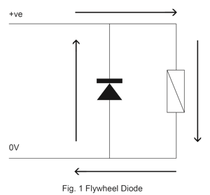 This works well, the diode blocks current from flowing when the coil is energised, but when the voltage is removed from the coil, the Back EMF is dissipated through the diode and not into the drive circuit. Current flows in a circular fashion which leads to another commonly used name for the Back EMF diode – the “Flywheel Diode”.
For most relays and contactors, a common diode used is the well established 1N4007 type or something similar. Ideally this diode should be physically positioned as close to the relay coil as possible. Durakool has several relays with an integral diode inside the relay cover itself. It is very common technique in automotive plug in relays such as the Durakool DG56, DG82 and DG85 types, but also in some industrial relays designed for socket mounting where it would be inconvenient to mount an external diode such as the Durakool DX4.
Although it is good at protecting the relay drive circuit, there is a downside to using a diode for Back EMF suppression. The coil inductance keeps the current flowing after the coil has been de-energised. This induced coil current is enough to keep the relay in the operated state, slow down the contact opening time or cause a bounce of the armature. For a typical automotive relay, like the Durakool DG85A, the opening time is less than 2ms, with a diode across the coil this can slow down to about 9 or even 10ms. This can be a source of problems when switching DC motor loads. When the power to the DC motor is turned off, if the motor keeps spinning, it acts as a generator and together with the motor inductance causes a high voltage to appear across the relay contacts as they open. This, in turn, results in a large arc which only extinguishes once the contacts have opened far enough to break the arc or the motor has come to rest. The final result is contact damage and eventually welding of the contacts. This time delay is often the cause of unexplained contact welding in relays switching DC motor loads. One point to note is that some integrated circuit relay drivers have built in diodes across the relay drive terminals, so it is possible to introduce a problem of delayed opening unintentionally. Another disadvantage is that the diode polarises the relay coil connections, they must be connected the correct way around or the relay will not operate as the diode will bypass the relay.
However, the automotive industry is well versed in switching DC motors; there a quite a few electric motors in the average vehicle. One solution, common in the automotive industry but often seen elsewhere is to use a resistor in parallel with the coil. (Fig. 2)
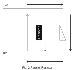 The resistor works by dissipating the Back EMF as heat but doesn’t delay the opening of the contacts as much as a diode. The typical opening time for a Durakool DG85A with resistor is about 2.5ms, at worst no more than 1ms longer than without the resistor. The downside is that the resistor + relay coil takes more current to operate but the relay coil terminals are not polarised and can be connected either way around. Another disadvantage is that the resistor and the relay coil must be calculated to work together for best effect, so the resistor is incorporated inside the relay. For example, the Durakool DG56A relay uses a 680Ω resistor for a nominal 12VDC coil and a 2700Ω resistor for a nominal 24VDC coil.
Another advantage of the resistor is that it’s generally an economical solution when compared to the alternatives. Durakool offers several relay series with an integral resistor, e.g. DG56, DG82 & DG85, which are used mainly in automotive applications. A resistor in parallel with the coil is not commonly seen used in industrial applications.
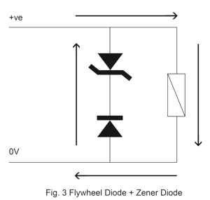
Although the diode and the resistor are the two most commonly seen Back EMF suppression techniques, especially among automotive relays, there are other methods, some of which are arguably better, even if more expensive. From a technical point of view, the best solution is a diode in series with a Zener diode and in parallel with the relay coil. (Fig. 3) This arrangement gives the optimum protection of the drive circuit whilst ensuring the minimum effect upon the relay opening time (typically around +0.5ms for a standard automotive relay). The main disadvantage of this technique is cost plus it’s difficult to include it inside a standard plug-in automotive relay.
 Other options with varying degrees of efficacy are bi-directional silicon transient suppressor diodes, and MOV’s (Metal-Oxide Varistor). A MOV may be cheaper than a bi-directional transient suppressor diode but typically has a higher clamping voltage so may not be suitable if the relay coil drive circuit cannot tolerate it. It is also possible to use a diode in series with a resistor, but considerable care must be taken with the choice of resistor and Durakool does not recommend this option. Finally, there is the resistor-capacitor “snubber” but it’s not a practical solution.